6F8A0917
11.3Cautionary Notes on Communications
Observe the following limitations when you communicate with flowmeter using HHT.
 Current output load
(1)Load resistance: 240Ω to 1kΩ (including communications line resistance)
(2)Load capacitance: 0.25 μF maximum (including communications line capacitance)
(3)Load inductance: 4mH maximum (including communications line inductance)
(For maximum cable length, about 2km is a guideline length when
 Wiring cable
Use a shielded cable (CVV-S, etc) for wiring.
 Interference on 4 to 20mA current signal
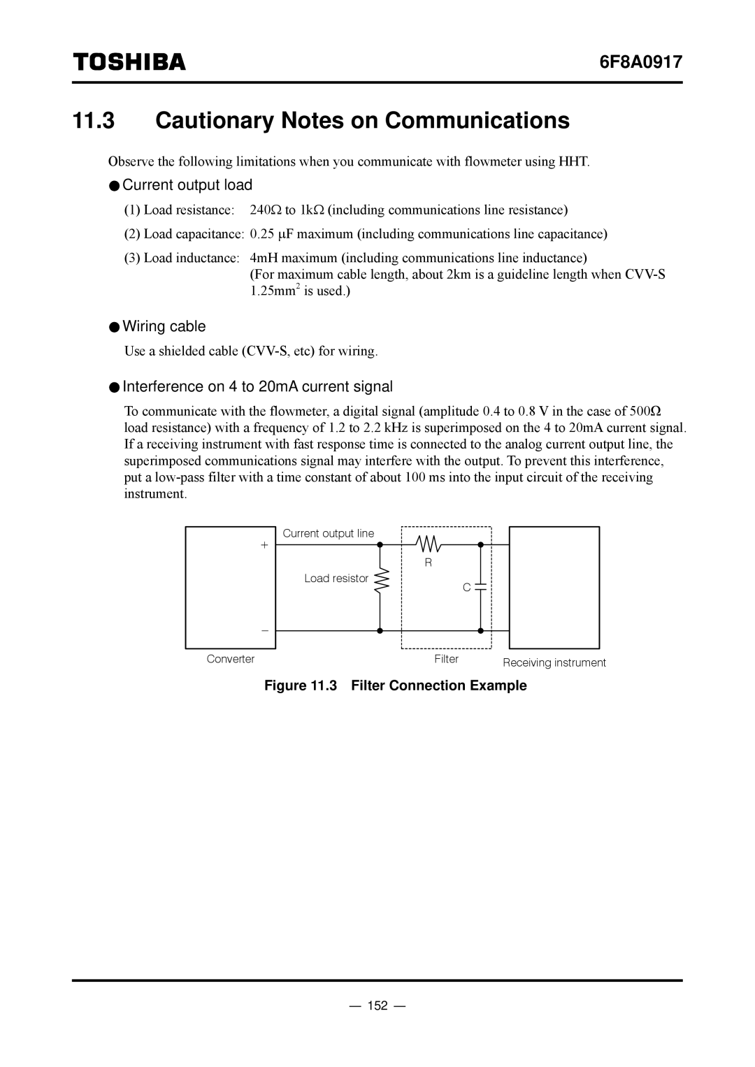
To communicate with the flowmeter, a digital signal (amplitude 0.4 to 0.8 V in the case of 500Ω load resistance) with a frequency of 1.2 to 2.2 kHz is superimposed on the 4 to 20mA current signal. If a receiving instrument with fast response time is connected to the analog current output line, the superimposed communications signal may interfere with the output. To prevent this interference, put a
| Current output line |
|
|
|
| R |
|
| Load resistor |
| C |
|
|
| |
Converter |
| Filter | Receiving instrument |
|
|
|