6F8A0917
(7) Error message / other message display
E X C U R R E N T O P E N
If an error or alarm condition occurs, a message is displayed in the 2nd line.
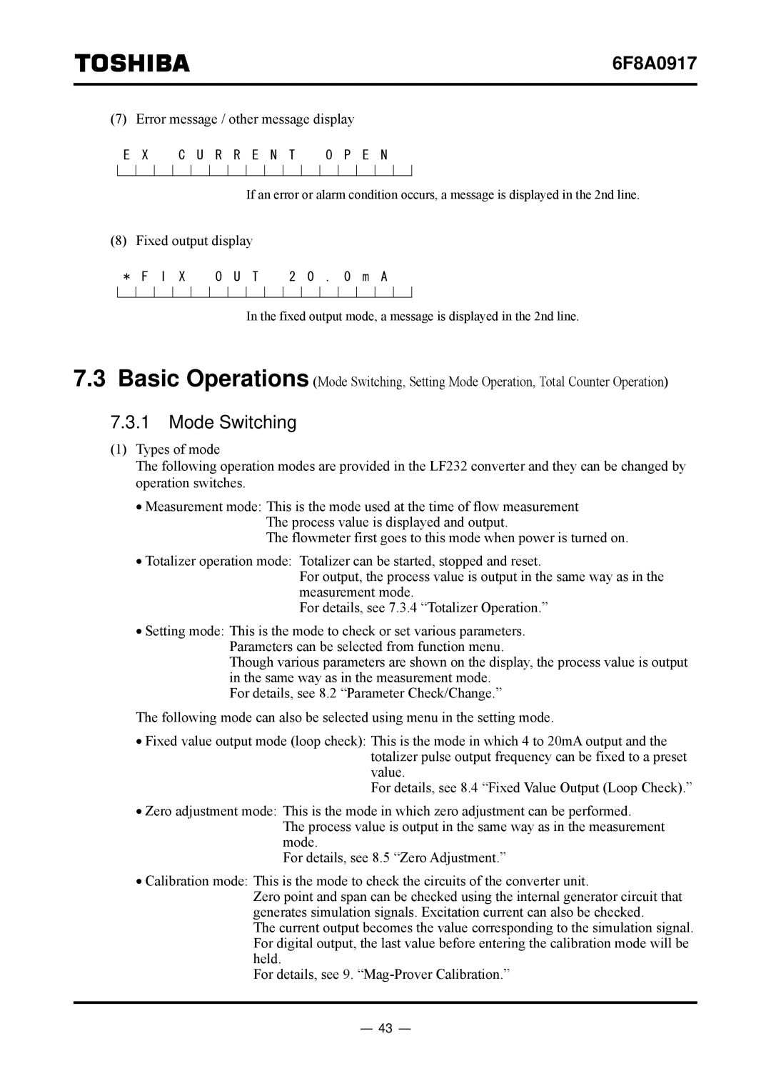
(8) Fixed output display
* F I X | O U T | 2 0 . 0 m A |
In the fixed output mode, a message is displayed in the 2nd line.
7.3Basic Operations (Mode Switching, Setting Mode Operation, Total Counter Operation)
7.3.1Mode Switching
(1)Types of mode
The following operation modes are provided in the LF232 converter and they can be changed by operation switches.
•Measurement mode: This is the mode used at the time of flow measurement The process value is displayed and output.
The flowmeter first goes to this mode when power is turned on.
•Totalizer operation mode: Totalizer can be started, stopped and reset.
For output, the process value is output in the same way as in the measurement mode.
For details, see 7.3.4 “Totalizer Operation.”
•Setting mode: This is the mode to check or set various parameters. Parameters can be selected from function menu.
Though various parameters are shown on the display, the process value is output in the same way as in the measurement mode.
For details, see 8.2 “Parameter Check/Change.”
The following mode can also be selected using menu in the setting mode.
•Fixed value output mode (loop check): This is the mode in which 4 to 20mA output and the totalizer pulse output frequency can be fixed to a preset value.
For details, see 8.4 “Fixed Value Output (Loop Check).”
•Zero adjustment mode: This is the mode in which zero adjustment can be performed.
The process value is output in the same way as in the measurement mode.
For details, see 8.5 “Zero Adjustment.”
•Calibration mode: This is the mode to check the circuits of the converter unit.
Zero point and span can be checked using the internal generator circuit that generates simulation signals. Excitation current can also be checked.
The current output becomes the value corresponding to the simulation signal. For digital output, the last value before entering the calibration mode will be held.
For details, see 9.
- 43 -