6F8A0917
7.4 Setting Menu List
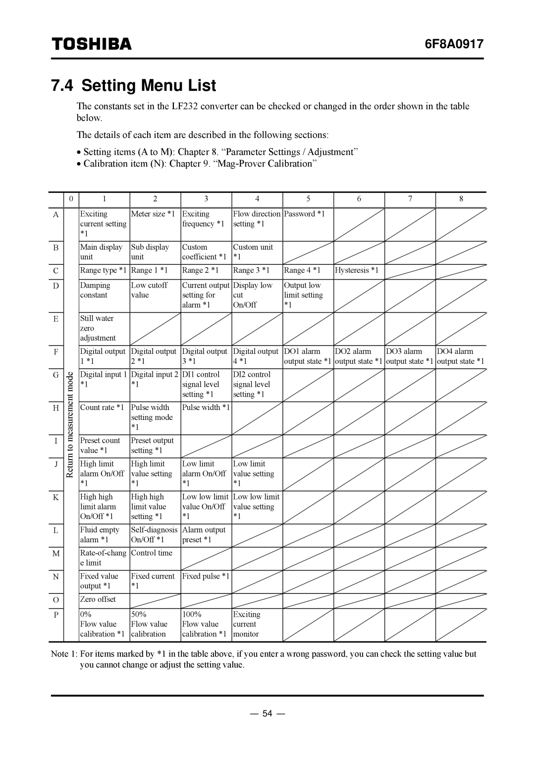
The constants set in the LF232 converter can be checked or changed in the order shown in the table below.
The details of each item are described in the following sections:
•Setting items (A to M): Chapter 8. “Parameter Settings / Adjustment”
•Calibration item (N): Chapter 9.
A
B
C
D
E
F
G
H
I
J
K
L
M
N
O
P
0
Return to measurement mode
1 | 2 | 3 | 4 | 5 | 6 | 7 | 8 |
|
|
|
|
|
|
|
|
Exciting | Meter size *1 | Exciting | Flow direction | Password *1 |
|
|
|
current setting |
| frequency *1 | setting *1 |
|
|
|
|
*1 |
|
|
|
|
|
|
|
|
|
|
|
|
|
|
|
Main display | Sub display | Custom | Custom unit |
|
|
|
|
unit | unit | coefficient *1 | *1 |
|
|
|
|
|
|
|
|
|
|
|
|
Range type *1 | Range 1 *1 | Range 2 *1 | Range 3 *1 | Range 4 *1 | Hysteresis *1 |
|
|
|
|
|
|
|
|
|
|
Damping | Low cutoff | Current output | Display low | Output low |
|
|
|
constant | value | setting for | cut | limit setting |
|
|
|
|
| alarm *1 | On/Off | *1 |
|
|
|
|
|
|
|
|
|
|
|
Still water |
|
|
|
|
|
|
|
zero |
|
|
|
|
|
|
|
adjustment |
|
|
|
|
|
|
|
|
|
|
|
|
|
|
|
Digital output | Digital output | Digital output | Digital output | DO1 alarm | DO2 alarm | DO3 alarm | DO4 alarm |
1 *1 | 2 *1 | 3 *1 | 4 *1 | output state *1 | output state *1 | output state *1 | output state *1 |
|
|
|
|
|
|
|
|
Digital input 1 | Digital input 2 | DI1 control | DI2 control |
|
|
|
|
*1 | *1 | signal level | signal level |
|
|
|
|
|
| setting *1 | setting *1 |
|
|
|
|
|
|
|
|
|
|
|
|
Count rate *1 | Pulse width | Pulse width *1 |
|
|
|
|
|
| setting mode |
|
|
|
|
|
|
| *1 |
|
|
|
|
|
|
|
|
|
|
|
|
|
|
Preset count | Preset output |
|
|
|
|
|
|
value *1 | setting *1 |
|
|
|
|
|
|
|
|
|
|
|
|
|
|
High limit | High limit | Low limit | Low limit |
|
|
|
|
alarm On/Off | value setting | alarm On/Off | value setting |
|
|
|
|
*1 | *1 | *1 | *1 |
|
|
|
|
|
|
|
|
|
|
|
|
High high | High high | Low low limit | Low low limit |
|
|
|
|
limit alarm | limit value | value On/Off | value setting |
|
|
|
|
On/Off *1 | setting *1 | *1 | *1 |
|
|
|
|
|
|
|
|
|
|
|
|
Fluid empty | Alarm output |
|
|
|
|
| |
alarm *1 | On/Off *1 | preset *1 |
|
|
|
|
|
|
|
|
|
|
|
|
|
Control time |
|
|
|
|
|
| |
e limit |
|
|
|
|
|
|
|
|
|
|
|
|
|
|
|
Fixed value | Fixed current | Fixed pulse *1 |
|
|
|
|
|
output *1 | *1 |
|
|
|
|
|
|
|
|
|
|
|
|
|
|
Zero offset |
|
|
|
|
|
|
|
|
|
|
|
|
|
|
|
0% | 50% | 100% | Exciting |
|
|
|
|
Flow value | Flow value | Flow value | current |
|
|
|
|
calibration *1 | calibration | calibration *1 | monitor |
|
|
|
|
|
|
|
|
|
|
|
|
Note 1: For items marked by *1 in the table above, if you enter a wrong password, you can check the setting value but you cannot change or adjust the setting value.
- 54 -
