4.22 DC FAN | 4 Replacement Procedure |
4.22 DC FAN
CAUTION: Do not apply pressure to the DC FAN.
Removing the DC FAN
To remove the DC FAN, follow the steps below and refer to Figure
1.Remove the following screws to remove H SINK PLT and screws fixing the VGA PLATE HOLDER (only for external graphics chip model).
• | M1.6⋅4C | OTHER screw | ⋅4 |
• | M1.6⋅4C | OTHER screw | ⋅2 (for external Graphics chip) |
NOTE: When removing the H SINK PLT or VGA PLATE HOLDER, be sure to remove the screws in the reverse order of the number marked on the heat.
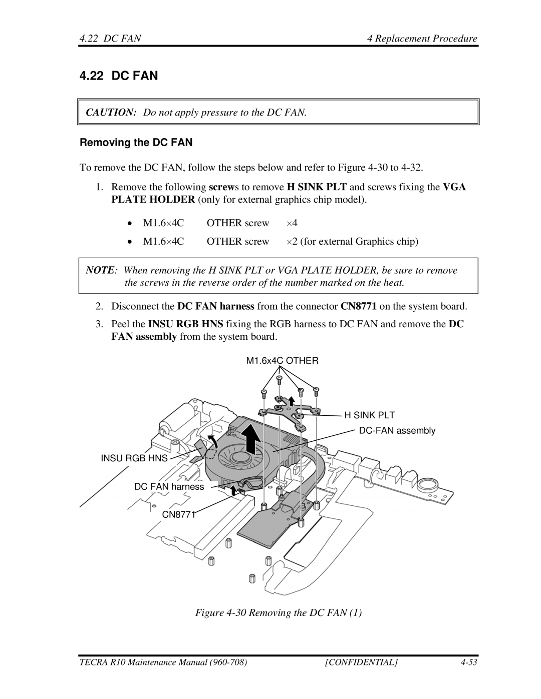
2.Disconnect the DC FAN harness from the connector CN8771 on the system board.
3.Peel the INSU RGB HNS fixing the RGB harness to DC FAN and remove the DC FAN assembly from the system board.
M1.6x4C OTHER
H SINK PLT
INSU RGB HNS ![]()
DC FAN harness
CN8771
Figure 4-30 Removing the DC FAN (1)
TECRA R10 Maintenance Manual | [CONFIDENTIAL] |