4.15 RTC battery4 Replacement Procedures
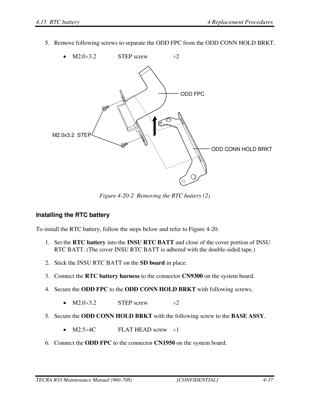
5. Remove following screws to separate the ODD FPC from the ODD CONN HOLD BRKT.
• M2.0⋅3.2 | STEP screw | ⋅2 |
ODD FPC
M2.0x3.2 STEP
ODD CONN HOLD BRKT
Figure 4-20-2 Removing the RTC battery (2)
Installing the RTC battery
To install the RTC battery, follow the steps below and refer to Figure
1.Set the RTC battery into the INSU RTC BATT and close of the cover portion of INSU RTC BATT. (The cover INSU RTC BATT is adhered with the
2.Stick the INSU RTC BATT on the SD board in place.
3.Connect the RTC battery harness to the connector CN9300 on the system board.
4.Secure the ODD FPC to the ODD CONN HOLD BRKT with following screws.
| • | M2.0⋅3.2 | STEP screw | ⋅2 |
5. | Secure the ODD CONN HOLD BRKT with the following screw to the BASE ASSY. | |||
| • | M2.5⋅4C | FLAT HEAD screw | ⋅1 |
6. | Connect the ODD FPC to the connector CN1950 on the system board. | |||
TECRA R10 Maintenance Manual | [CONFIDENTIAL] |
