4 Replacement Procedures
Figures |
|
|
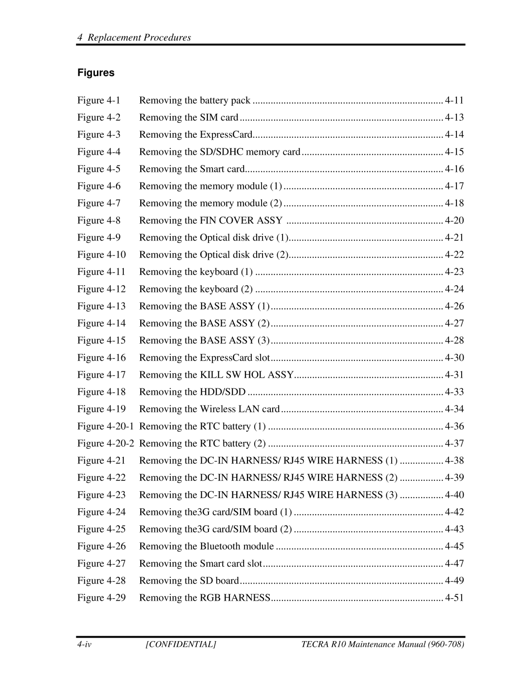
Figure | Removing the battery pack | |
Figure | Removing the SIM card | |
Figure | Removing the ExpressCard | |
Figure | Removing the SD/SDHC memory card | |
Figure | Removing the Smart card | |
Figure | Removing the memory module (1) | |
Figure | Removing the memory module (2) | |
Figure | Removing the FIN COVER ASSY | |
Figure | Removing the Optical disk drive (1) | |
Figure | Removing the Optical disk drive (2) | |
Figure | Removing the keyboard (1) | |
Figure | Removing the keyboard (2) | |
Figure | Removing the BASE ASSY (1) | |
Figure | Removing the BASE ASSY (2) | |
Figure | Removing the BASE ASSY (3) | |
Figure | Removing the ExpressCard slot | |
Figure | Removing the KILL SW HOL ASSY | |
Figure | Removing the HDD/SDD | |
Figure | Removing the Wireless LAN card | |
Figure | ||
Figure | ||
Figure | Removing the | |
Figure | Removing the | |
Figure | Removing the | |
Figure | Removing the3G card/SIM board (1) | |
Figure | Removing the3G card/SIM board (2) | |
Figure | Removing the Bluetooth module | |
Figure | Removing the Smart card slot | |
Figure | Removing the SD board | |
Figure | Removing the RGB HARNESS | |
[CONFIDENTIAL] | TECRA R10 Maintenance Manual |
