Vanguard Managed Solutions
Restricted Rights Legend
Restricted Rights Notification for U.S. Government Users
Radio Frequency Interference Regulations
Proprietary Material
Telecommunications Regulations
Contents
Vanguard 7300 Installation
Modifying Your Vanguard
Glossary Return Procedure Index
Comments About
Customer Information
Customer
Questions
Page
Customer Response Card
Page
Vanguard Applications Platform Version
Vanguard 7300 Functions and Features
Overview
Introduction
Version
Vanguard 7300 Functions and Features
Vanguard Applications Ware functions
2shows available Vanguard 7300 Version 2 Series routers
Scalable Hardware Platforms Version
Information
Detailed
Series, refer to the Software Release Notice
Advanced Encryption Card AEC
Compression
Frame Relay to ATM Environment
Vanguard 7300 Applications
Vanguard 7310 Used for High-Speed LAN IP Routing
Multiservice IP, SNA, Serial, and Voice Traffic
Multiservice IP SNA, Serial Voice Traffic
Speed WAN Ports
Regional
Concentrator with
Multiple Low
7300’s
Solution Using
Large Networking
Multiple Vanguard
Vanguard 7300 Platform Version
Routers
Without disconnecting unrelated cables
Vanguard 7300 Chassis Version
7310
10 Midplane and Card Connectors, Cutaway Diagram
Vanguard 7300 Platform Version
Chassis front
Vanguard 7300 Revision 2 Series router, refer to Figure
Chassis rear
Depending on its purpose, a CompactPCI card can be
Vanguard 7300 Cards
Description
Low-level software customizing is eliminated
Bus Type Connector Purpose
CompactPCI Connectors
14. CompactPCI Connectors Front View
Vanguard 7300 Cards
Are discussed
Enclosures
Vanguard
Feature Vanguard Version
Enclosures
Vanguard 7300 Version 1 Series Enclosure Views
Front Panel Vanguard Version Enclosure
Vanguard Enclosure Features Version
Vanguard 7310 Version 1 Enclosure
Rear Vanguard Version Enclosure
Vanguard Version 1 Chassis Dimensions
Vanguard 7330 Version 1 Enclosure
Vanguard Version Enclosure Features Enclosure, Front Panel
Rear View
Connectors
Version Removable Filler Panels
Vanguard 7310 and 7330 Version 2 Enclosure, Front View
Vanguard 7310 and 7330 Version 2 Enclosure
Vanguard 7310 and 7330 Version 2 Enclosure Rear View
Module connectors
Chassis
Depth 13.4 inches Weight 22 lbs
Assemblies
Central Processor Unit CPU Cards on
Vanguard 7300 Cards
Series routers
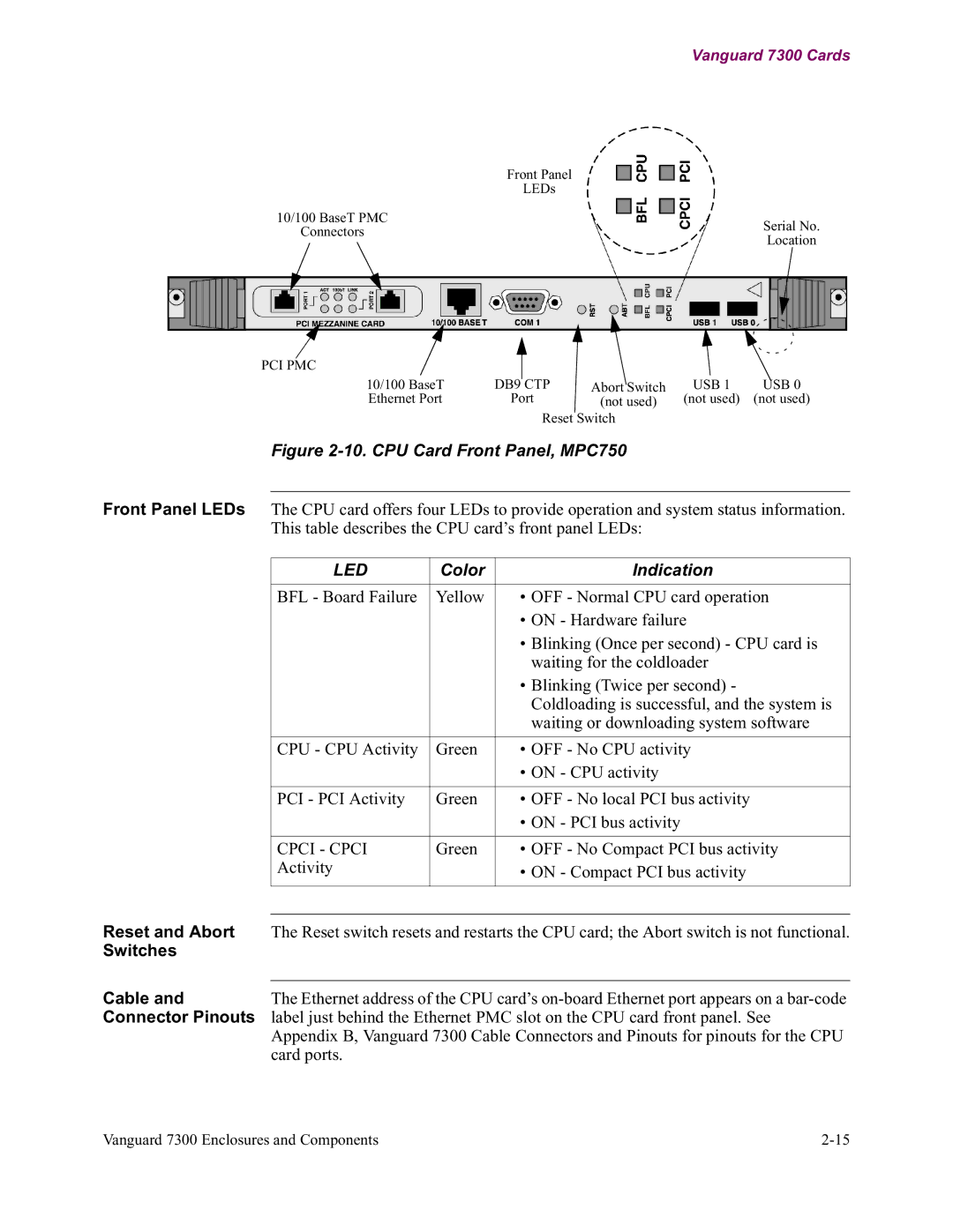
Central Processor Unit CPU Card MPC750
Central Processor Unit CPU Cards
Card PMC
Installation
CPU Card
PCI Mezzanine
Color Indication
Switches
512MB RAM
Central Processor Unit CPU Card IBM750FX
Range AUTO, 1000FD, 100FD, 100HD, 10FD, 10HD Default
Mode Port Operating Mode
Port Number
PCI Mezzanine Card PMC Support Front Panel
Yellow LED Green LED State Interpretation
RJ45 Connector
LEDs
Abort/Reset Switch
13. Carrier Expansion Card with Two PMCs
Carrier Expansion Card
Pinouts
Green On Receiving power
Blue Not Used
Front View
PCI Mezzanine Card PMC
Dual-port 10/100BaseT Ethernet Mezzanine Card PMC
Cable
T1/E1/PRI Card Functions T1/E1/PRI Timing Considerations
T1/E1/PRI Card and Rear Transition Module
T1/E1/PRI Card
T1/E1/PRI Rear Transition Module
On the underside of the card, near the left most PMC slot
T1/E1/PRI Card
Rear Panel
Voice Server/DSP Mezzanine Card PMC
Functionality
T3/E3 ATM Card
Carrier Expansion Card
Profile
Mezzanine Card installed and T3/E3 Rear Transition Module
T3/E3 Rear Transition Module
T3/E3 ATM Card
T3/E3 Rear
Accessible from the rear of the chassis as shown in Figure
Transition Module cabling
Rear Panel LEDs
System status information
Cabling
ATM Compression Support
Main Menu-Configure-Configure Network Services
T3/E3 ATM Mezzanine Card PMC
Source aam-10s1 Destination lcon-1
Step Action
Supported
Serial Card and Rear Transition Module
Serial Card
Serial Protocols
Speeds listed in the following table
Serial Rear Transition Module
Baud-Rate
Generator
T1/E1 Card
Clock Timing
Timing
Clocked Port as DCE Port as DTE
Clock
25. Clocking Example
26. Serial Transition Module Rear View
Module Rear View
Token Ring Card Functions
Token Ring Card
Green Not Used
28. Token Ring Card Side View
Standard AES
Advanced
Encryption
Encryption Card
Installation
Benefits
Encryption Card
Connecting Vanguard 7300 DC Power
How to Choose a Site
Installing the Vanguard 7300 in a Rack
Attaching a Vanguard 7300 AC Power Cord
Completed Task Description
AC power cords
Checklist
Before You Begin
Checking Your Shipment Contents
Typical Vanguard 7330 Version 1 Contents
Missing Parts
Case
Damaged or
How to Choose a Site
Fan
Electrostatic Discharge Precautions
Precautions
Thermal Considerations
Version 2 enclosure
For ease in access and cabling. -4 and -5 show the hinged
Removing And Replacing Vanguard 7300 Front Covers
Vanguard 7310 and 7330 Version 2 Front Cover Panel
Vanguard Version 1 Front Covers
Procedures
Removing
Replacing
Vanguard 7310 Version 1 Cable Channel
Step
Recabling
Front panel
Vanguard Version 1 Front Cover Panels
Hinge pin. Rotate the pin into its lock position
Vanguard 7330 Version 1 Cable Channel
Vanguard 7330 Version Front Cable Cover
Front Cover Panels
Grounding
Installing the Vanguard 7300 in a Rack
10. Rack Mount Hardware Locations Vanguard
Procedure for Rack-mounting Version 1 Rack- mounting
11. Rack-Mount Locations Vanguard 7330 Version
Version 2 Rack- mounting
Attaching
Attaching a Vanguard 7300 AC Power Cord
Power Cord
Switch
Chassis front panel
15. Vanguard 7330 Version 2 Power Connectors
Version 1 Series routers that have DC power supplies
Connecting Vanguard 7300 DC Power
Are located as shown in Figure
Connecting DC Power to a Vanguard 7310 Version
Wiring a Vanguard
Version 1 DC Power Supply
Pin Number Description
Quality AMP Part Description
Vanguard 7300 DC Power Terminal Block
Connecting DC Power to a Vanguard 7330 Version
Power supply, shown in -18 and -21. The detailed diagram
Supply
Two blocks
Vanguard Version 2 DC Power Terminal Block
Wiring a Vanguard 7310 and 7330 Version 2 DC Power Supply
For any optional cards pre-installed in your 7300 router
Cabling Procedures
MPC750 CPU Card
CPU Cards
Operator Console
Connectors on the front of the CPU card are show in -23.The
IBM750FX CPU Card
Cable the IBM750FX CPU
24. Carrier Expansion Card Connectors
T1/E1/PRI Card
Functionality
As shown in Figure
Cabling the T3/E3
Type DTE Cable Plug DCE Cable Socket
Serial Card
Card
29. Token Ring Connections
Platform and discusses these topics
Power-Up Procedure
Accessing the Control Terminal Port
Vanguard 7300 Port Configuration
Meaning Color Indication
Power-Up Procedure
Accessing the Control Terminal Port
A Sample Boot Console Display T1/E1/PRI Cards
A Sample Boot Console Display, Serial Cards
Previously loaded operating software Applications Ware
Loading Software
Format
Vanguard 7300 Port Configuration
Port Numbering
Port Number
Types of CPU cards supported in the Vanguard 7300 Series
Vanguard 7300 Card Configuration Port Numbers
CPU Card Port
Numbers
CPU Card Ports
Port Numbers -- Serial/T1/E1/PRI Rear Transition Modules
Port Speed
Configured Port Speed on FRI Port Statistics Display
LLC-SDLC LAN Station Tables
Part Number T0101-09
Conversion
Was not designed for batch file transfer
Dynamic Coder for H.323
Voice Port Configuration
Devices. This feature is limited to H.323 calls only
Accessing Configuring Dynamic Coder
Coder Parameter Dynamic Coder
Port Configuration Menu
Dynamic Modem
Accessing Configuring Dynamic Modem
Parameter Dynamic Modem
Type = H323
Virtual Port Menu using the H.323 Options selection
Alternate Gatekeeper
Block Alerting
Range
Configuring Block Alerting Parameter
Address Registration
Options
11. FXS Port and FXS Virtual Port Menu
Addresses
Configuring Local Subscriber Address
Board Management
Involved in the fault to continue operation
Configuration
Keepalive Timeout
History Limit
Keepalive Tries
Failure Threshold Time
Failure Threshold Count
Activate Board
Booting
Control
Deactivate Board
Summary Statistics
Status
Statistics menu, the following menu items will be listed
Statistics
Reset Board
Management
Board Management statistics
Board Management History Reset
History Log
Receives the prompt
Page
PMCs section on
General Card Replacement Guidelines section on
Cards
Section on
Cards into the Vanguard 7300 enclosure
General Card Replacement Guidelines
Chassis Card and Transition Module Guides 7330 Version
Or Transition
With the adjacent cards and/or slot covers
Chapter
Inserting components requires careful handling
Levers are in the open position. Refer to Figure
Inserting a CompactPCI Card or Transition Module
Vanguard 7300 Card Installation Order
CPU Card Installation Guidelines 7300 Version
10/100BaseT Ethernet PMC
CPU Card Installation Guidelines 7310 and 7330 Version
Token Ring Card
With Voice DSP
Serial Card
Before You Begin
This section provides procedures that explain
Removing and Replacing the CPU Card CPU Mezzanine Card PMC
Removing and Replacing the MPC750 CPU Card
Vanguard 7300 MPC750 CPU Card with Pre-Installed Memory PMC
8show the location where PMCs can be installed
Installing Mezzanine Cards PMCs on the MPC750 CPU Card
Installing the Ethernet PMC on the MPC750 CPU Card
IBM750FX CPU
Installing Mezzanine Cards PMCs on the IBM750FX CPU Card
Installing an
Ethernet PMC on
11. Installing the Ethernet PMC on the IBM750FX CPU Card
Reinstalling
Reinstalling the CPU Card
Cards and Modules section on page 5-2before you begin
Hot Swap
Carrier Expansion
Removing the Carrier Expansion Card
Expansion Card
Installing Ethernet PMCs on the Carrier Expansion Card
Populating
13. Installing Ethernet PMCs on the Carrier Expansion Card
Replacing the Carrier Expansion Card
14. T1/E1/PRI Card and Rear Transition Module Orientation
Open the ejector levers on the T1/E1/PRI card
Replacement Guidelines section on page 5-2 before you begin
Installing
Removing and Replacing the T1/E1/PRI Card
T1/E1/PRI Rear
Removing and Replacing the T1/E1/PRI Rear Transition Module
E1/PRI Rear
Transition Module
Installing a Voice Server PMC on a T1/E1/PRI Card
Installing the Voice Server DSP Mezzanine Card PMC
Removing and Replacing the T3/E3 Rear Transition Module
Module. This section provides procedures that explain
Installing the T3/E3 ATM Mezzanine Card PMC
Removing and Replacing the T3/E3 ATM Card
ATM Card
Removing and Replacing the T3/E3 ATM Card
E3 ATM Card
Vanguard 7300 chassis
Removing and Replacing the T3/E3 Rear Transition Module
Open the ejector levers on the T3/E3 Rear Transition Module
Installing a T3/E3 ATM PMC onto a Carrier Expansion Card
Installing the T3/E3 ATM Mezzanine Card PMC
Cards and Modules section on page 5-2 before you begin
Removing and Replacing the Serial Card
You feel resistance
Enclosurethe Serial Rear Transition Module
Open the ejector levers on the Serial Card
Serial Rear
Removing and Replacing the Serial Rear Transition Module
Until you feel resistance
Removing and Replacing the Token Ring Card
Slot
Module and remove the module from the card connectors
Installing and Removing the Advanced Encryption Card AEC
PMC
Supplies and cooling fans
Procedures
Replacing Power Supplies and Cooling Fans, 7310 Version
Accessible from the rear of the enclosure
Is accessible from the front of the enclosure
Not hot-swappable on the Vanguard 7310 Version
Removing and Installing the Power Supply/Inlet Fan Module
From both AC and DC-powered Vanguard 7310 routers
Reconnect the power to the unit
Reverse these procedures and reconnect power to the unit
Removing and Installing the Power Input Module
Installation
Wrong power unit in the wrong Vanguard 7310 enclosure
Refer to -4and these steps to remove the Exhaust Fan Module
Removing and Installing the Exhaust Fan Module
Power and without disrupting system service
Replacing Power Supplies and Cooling Fans, 7330 Version
Removing the Fan Tray
Installing or Removing the Fan Tray
Description Removing Replacing the AC Power Supply
Procedures
Assembly in the Vanguard 7330 Version 1chassis
Chassis Mounting Screws
Removing and Replacing the Vanguard 7310 and 7330 Version
Removing and Installing the Intake Fan Module
Explain
Wartungsbestimmungen außer Kraft setzen
Maintenance
Chassis
Loosen the 1 mounting screw of the power supply
Front panel power switch
Exhaust Fan Module
Without disrupting system service
Refer to -8and these steps to remove the Exhaust Fan Module
Fan Module
Removing and Installing the Intake Fan Module
Section on page A-8
Vanguard 7310 and 7330 Version 2 Product Specifications
Slots
Vanguard 7310 Version 1 Product Specifications
Introduction Chassis Dimensions
Mounting Hot-Swappable Mid-plane
Cooling
These are the electrical specifications
These are the cooling specifications
Electrical
Temperature and Environmental
System CPU Slot Hot Swap Specification
Vanguard 7330 Version 1 Product Specifications
Introduction Chassis Dimensions Chassis Weight
Electrical Power Supplies and Cooling
Temperature and Environmental
Vanguard 7310 and 7330 Version 2 Product Specifications
DC Power Supply
Forced Air Cooling
Cable Type Vanguard 7300 Card Connectors Length
Connectors
Table lists the RJ45 pinout on the IBM750FX CPU card
CPU Card Connector and Cable Details
Pin Signal
Mbps 10/100
LAN Interface
Ethernet Port
Ethernet Mezzanine Card Connector and Cable Details
Connector
RJ45 10/100BaseT
Pin Function
T1/E1/PRI Cables
T3/E3 ATM Cables
Serial Card Connector and Cable Details
Pin
Rxclkb
Txda Rxda Rtsa Ctsa Dsra
UTP RJ45
Token Ring Card Connector and Cable Details
This table describes the UTP connector pinout
This table describes the STP connector pinout
Version 2 DC
AC and DC Power Connections
Power Terminal Block
Vanguard 7310
Cables
Ordering Vanguard
AC and DC Power Connections
This appendix provides information about the following
Appendix C
Interface Type
How to Order
Service Code Facility Interface
Connections
Equipment
Customer-Provided
Telephone
CE Marking
Product Declarations and Regulatory Information
Product Declarations and Regulatory Information
Page
Term Meaning
Vanguard 7300 Glossary of Terms Introduction
Link Access Protocol-Balanced
Frame Relay Access Protocol Frame Relay Adapter frame
Frame Relay Access Device
Integrated Services Digital Network a special Telco service
RS-232 Recommended Standard Serial device connector See EIA
Public Switched Telephone Network
QoS Quality of Service
Database for authenticating modem and Isdn connections
Virtual Local Area Network
Console terminal command-line utility
User Datagram Protocol
Voice Activity Detection
For Locations Contact
Return Procedures Introduction
Equipment Return
Factory Repair
Packaging
Guidelines for
Index
7330 3-13,3-14Clearances 3-6Pinouts B-7Specifications B-1
Page
WAN