FT-950
Operating Manual
Packet Setup (Including Subcarrier Frequency)
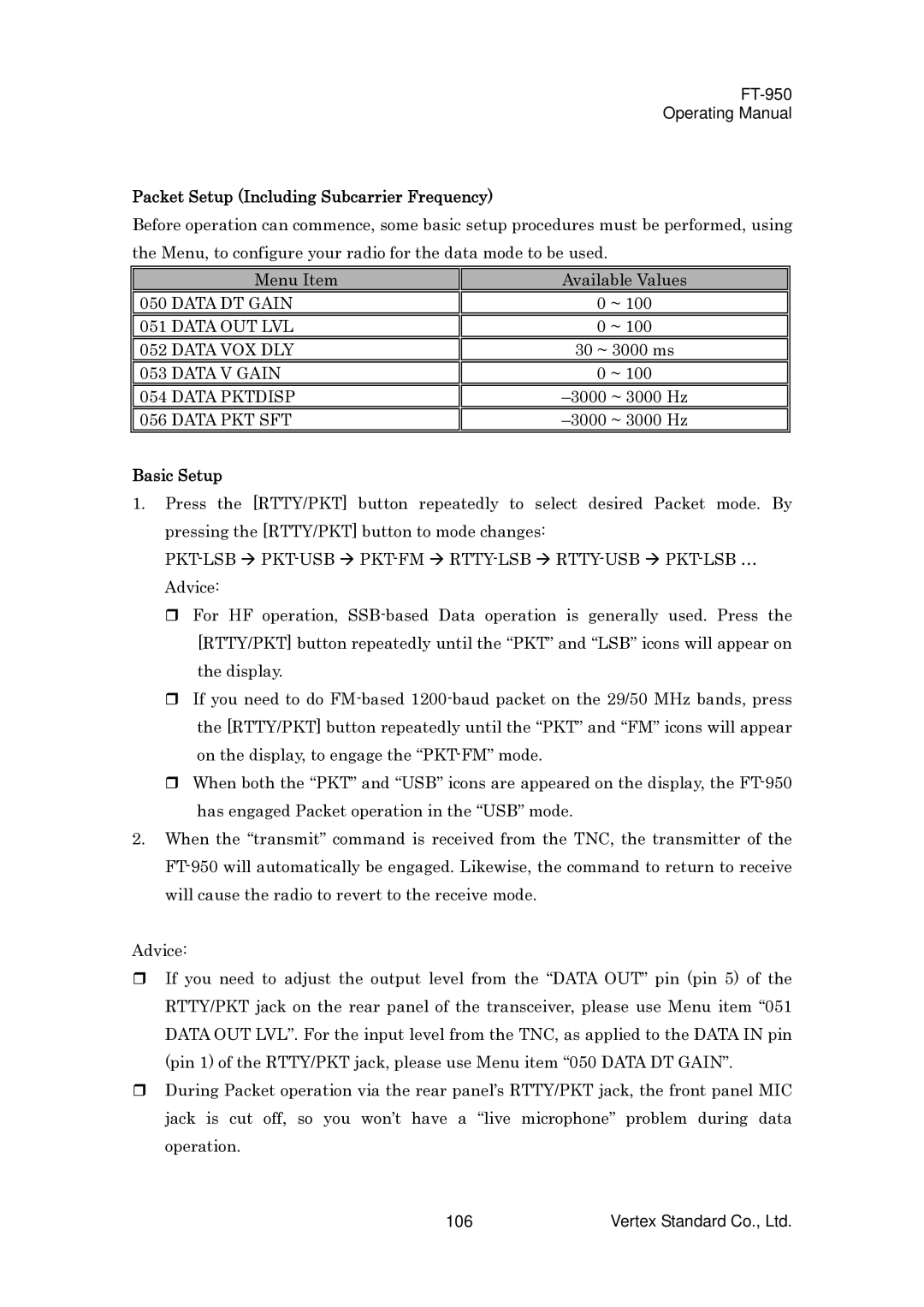
Before operation can commence, some basic setup procedures must be performed, using the Menu, to configure your radio for the data mode to be used.
Menu Item | Available Values | |
|
|
|
050 DATA DT GAIN | 0 | ~ 100 |
|
|
|
051 DATA OUT LVL | 0 | ~ 100 |
|
| |
052 DATA VOX DLY | 30 ~ 3000 ms | |
|
|
|
053 DATA V GAIN | 0 | ~ 100 |
|
| |
054 DATA PKTDISP | ||
|
| |
056 DATA PKT SFT | ||
|
|
|
Basic Setup
1.Press the [RTTY/PKT] button repeatedly to select desired Packet mode. By pressing the [RTTY/PKT] button to mode changes:
For HF operation,
If you need to do
When both the “PKT” and “USB” icons are appeared on the display, the
2.When the “transmit” command is received from the TNC, the transmitter of the
Advice:
If you need to adjust the output level from the “DATA OUT” pin (pin 5) of the RTTY/PKT jack on the rear panel of the transceiver, please use Menu item “051 DATA OUT LVL”. For the input level from the TNC, as applied to the DATA IN pin (pin 1) of the RTTY/PKT jack, please use Menu item “050 DATA DT GAIN”.
During Packet operation via the rear panel’s RTTY/PKT jack, the front panel MIC jack is cut off, so you won’t have a “live microphone” problem during data operation.
106 | Vertex Standard Co., Ltd. |
