|
|
| Technical information |
|
| Table | |||
|
|
|
|
|
| Reliable stacking may be | Less reliable stacking may |
|
|
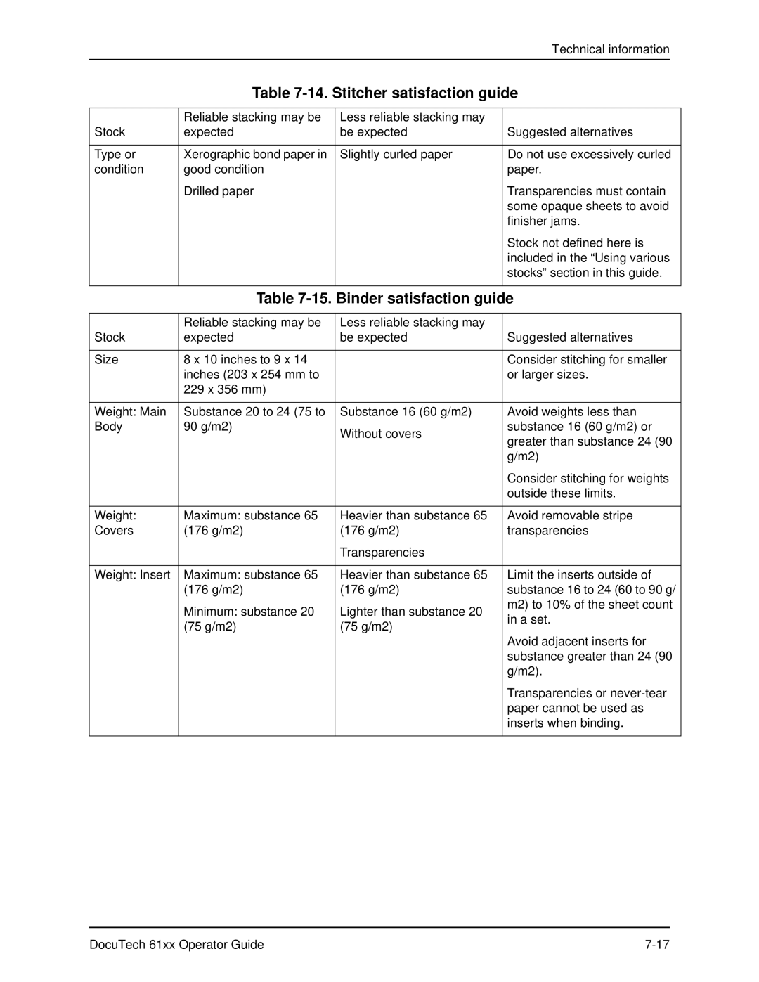
Stock | expected | be expected | Suggested alternatives | |
|
|
|
| |
Type or | Xerographic bond paper in | Slightly curled paper | Do not use excessively curled | |
condition | good condition |
| paper. | |
| Drilled paper |
| Transparencies must contain | |
|
|
| some opaque sheets to avoid | |
|
|
| finisher jams. | |
|
|
| Stock not defined here is | |
|
|
| included in the “Using various | |
|
|
| stocks” section in this guide. | |
|
|
|
| |
| Table | |||
|
|
|
|
|
| Reliable stacking may be | Less reliable stacking may |
|
|
Stock | expected | be expected | Suggested alternatives | |
|
|
|
| |
Size | 8 x 10 inches to 9 x 14 |
| Consider stitching for smaller | |
| inches (203 x 254 mm to |
| or larger sizes. | |
| 229 x 356 mm) |
|
|
|
|
|
|
| |
Weight: Main | Substance 20 to 24 (75 to | Substance 16 (60 g/m2) | Avoid weights less than | |
Body | 90 g/m2) | Without covers | substance 16 (60 g/m2) or | |
|
| greater than substance 24 (90 | ||
|
|
| ||
|
|
| g/m2) | |
|
|
| Consider stitching for weights | |
|
|
| outside these limits. | |
|
|
|
| |
Weight: | Maximum: substance 65 | Heavier than substance 65 | Avoid removable stripe | |
Covers | (176 g/m2) | (176 g/m2) | transparencies | |
|
| Transparencies |
|
|
|
|
|
| |
Weight: Insert | Maximum: substance 65 | Heavier than substance 65 | Limit the inserts outside of | |
| (176 g/m2) | (176 g/m2) | substance 16 to 24 (60 to 90 g/ | |
| Minimum: substance 20 | Lighter than substance 20 | m2) to 10% of the sheet count | |
| in a set. | |||
| (75 g/m2) | (75 g/m2) | ||
|
|
| ||
|
|
| Avoid adjacent inserts for | |
|
|
| substance greater than 24 (90 | |
|
|
| g/m2). | |
|
|
| Transparencies or | |
|
|
| paper cannot be used as | |
|
|
| inserts when binding. | |
|
|
|
|
|
DocuTech 61xx Operator Guide |