Pinout Descriptions
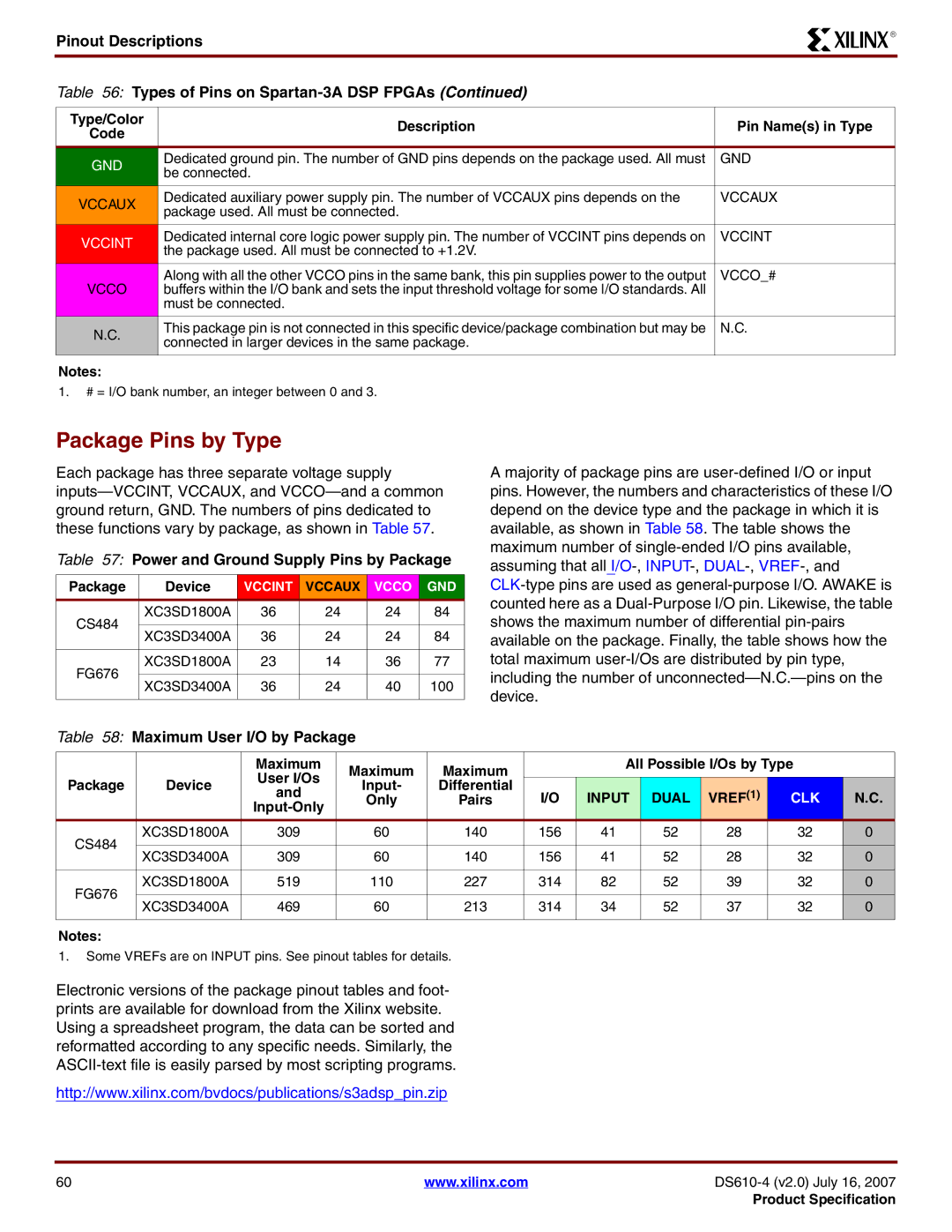
Table 56: Types of Pins on Spartan-3A DSP FPGAs (Continued)
R
Type/Color | Description | Pin Name(s) in Type | |
Code | |||
|
| ||
GND | Dedicated ground pin. The number of GND pins depends on the package used. All must | GND | |
be connected. |
| ||
|
| ||
VCCAUX | Dedicated auxiliary power supply pin. The number of VCCAUX pins depends on the | VCCAUX | |
package used. All must be connected. |
| ||
|
| ||
VCCINT | Dedicated internal core logic power supply pin. The number of VCCINT pins depends on | VCCINT | |
the package used. All must be connected to +1.2V. |
| ||
|
| ||
| Along with all the other VCCO pins in the same bank, this pin supplies power to the output | VCCO_# | |
VCCO | buffers within the I/O bank and sets the input threshold voltage for some I/O standards. All |
| |
| must be connected. |
| |
N.C. | This package pin is not connected in this specific device/package combination but may be | N.C. | |
connected in larger devices in the same package. |
| ||
|
| ||
|
|
|
Notes:
1.# = I/O bank number, an integer between 0 and 3.
Package Pins by Type
Each package has three separate voltage supply
Table 57: Power and Ground Supply Pins by Package
Package | Device | VCCINT | VCCAUX | VCCO | GND | |
CS484 | XC3SD1800A | 36 | 24 | 24 | 84 | |
|
|
|
|
| ||
XC3SD3400A | 36 | 24 | 24 | 84 | ||
| ||||||
|
|
|
|
|
| |
FG676 | XC3SD1800A | 23 | 14 | 36 | 77 | |
|
|
|
|
| ||
XC3SD3400A | 36 | 24 | 40 | 100 | ||
| ||||||
|
|
|
|
|
|
Table 58: Maximum User I/O by Package
Amajority of package pins are
|
| Maximum | Maximum | Maximum |
| All Possible I/Os by Type |
| ||||
Package | Device | User I/Os |
|
|
|
|
|
| |||
Input- | Differential |
|
|
|
|
|
| ||||
and | I/O | INPUT | DUAL | VREF(1) | CLK | N.C. | |||||
|
| Only | Pairs | ||||||||
|
|
|
|
|
|
|
|
|
|
| |
CS484 | XC3SD1800A | 309 | 60 | 140 | 156 | 41 | 52 | 28 | 32 | 0 | |
|
|
|
|
|
|
|
|
|
| ||
XC3SD3400A | 309 | 60 | 140 | 156 | 41 | 52 | 28 | 32 | 0 | ||
| |||||||||||
|
|
|
|
|
|
|
|
|
|
| |
FG676 | XC3SD1800A | 519 | 110 | 227 | 314 | 82 | 52 | 39 | 32 | 0 | |
|
|
|
|
|
|
|
|
|
| ||
XC3SD3400A | 469 | 60 | 213 | 314 | 34 | 52 | 37 | 32 | 0 | ||
| |||||||||||
|
|
|
|
|
|
|
|
|
|
| |
Notes:
1.Some VREFs are on INPUT pins. See pinout tables for details.
Electronic versions of the package pinout tables and foot- prints are available for download from the Xilinx website. Using a spreadsheet program, the data can be sorted and reformatted according to any specific needs. Similarly, the
http://www.xilinx.com/bvdocs/publications/s3adsp_pin.zip
60 | www.xilinx.com | |
|
| Product Specification |