Installation
Test Set Familiarization
Rear Panel
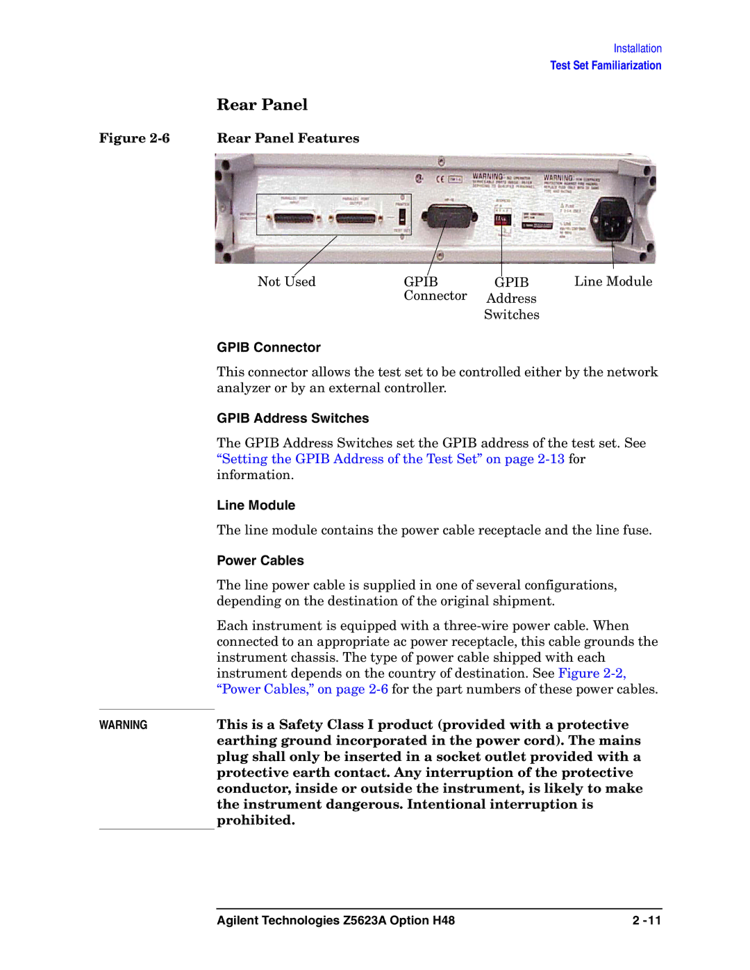
Figure 2-6 Rear Panel Features
|
|
|
|
|
|
|
| Line Module |
|
|
|
|
|
|
|
| |
|
| Not Used | GPIB |
|
| GPIB | ||
|
| |||||||
|
|
| Connector | Address |
| |||
|
|
|
|
| Switches |
| ||
| GPIB Connector |
|
|
|
|
|
| |
| This connector allows the test set to be controlled either by the network | |||||||
| analyzer or by an external controller. |
|
|
|
| |||
| GPIB Address Switches |
|
|
|
|
|
| |
| The GPIB Address Switches set the GPIB address of the test set. See | |||||||
| “Setting the GPIB Address of the Test Set” on page | |||||||
| information. |
|
|
|
|
|
| |
| Line Module |
|
|
|
|
|
| |
| The line module contains the power cable receptacle and the line fuse. | |||||||
| Power Cables |
|
|
|
|
|
| |
| The line power cable is supplied in one of several configurations, | |||||||
| depending on the destination of the original shipment. |
| ||||||
| Each instrument is equipped with a | |||||||
| connected to an appropriate ac power receptacle, this cable grounds the | |||||||
| instrument chassis. The type of power cable shipped with each | |||||||
| instrument depends on the country of destination. See Figure | |||||||
| “Power Cables,” on page | |||||||
| This is a Safety Class I product (provided with a protective | |||||||
WARNING | ||||||||
| earthing ground incorporated in the power cord). The mains | |||||||
plug shall only be inserted in a socket outlet provided with a protective earth contact. Any interruption of the protective conductor, inside or outside the instrument, is likely to make the instrument dangerous. Intentional interruption is prohibited.
Agilent Technologies Z5623A Option H48 | 2 |
