Installation
Connecting and Turning on the Test Set
NOTE | The test set is shipped from the factory with the GPIB address set to 12. |
Table
NOTE
Connecting and Turning on the Test Set
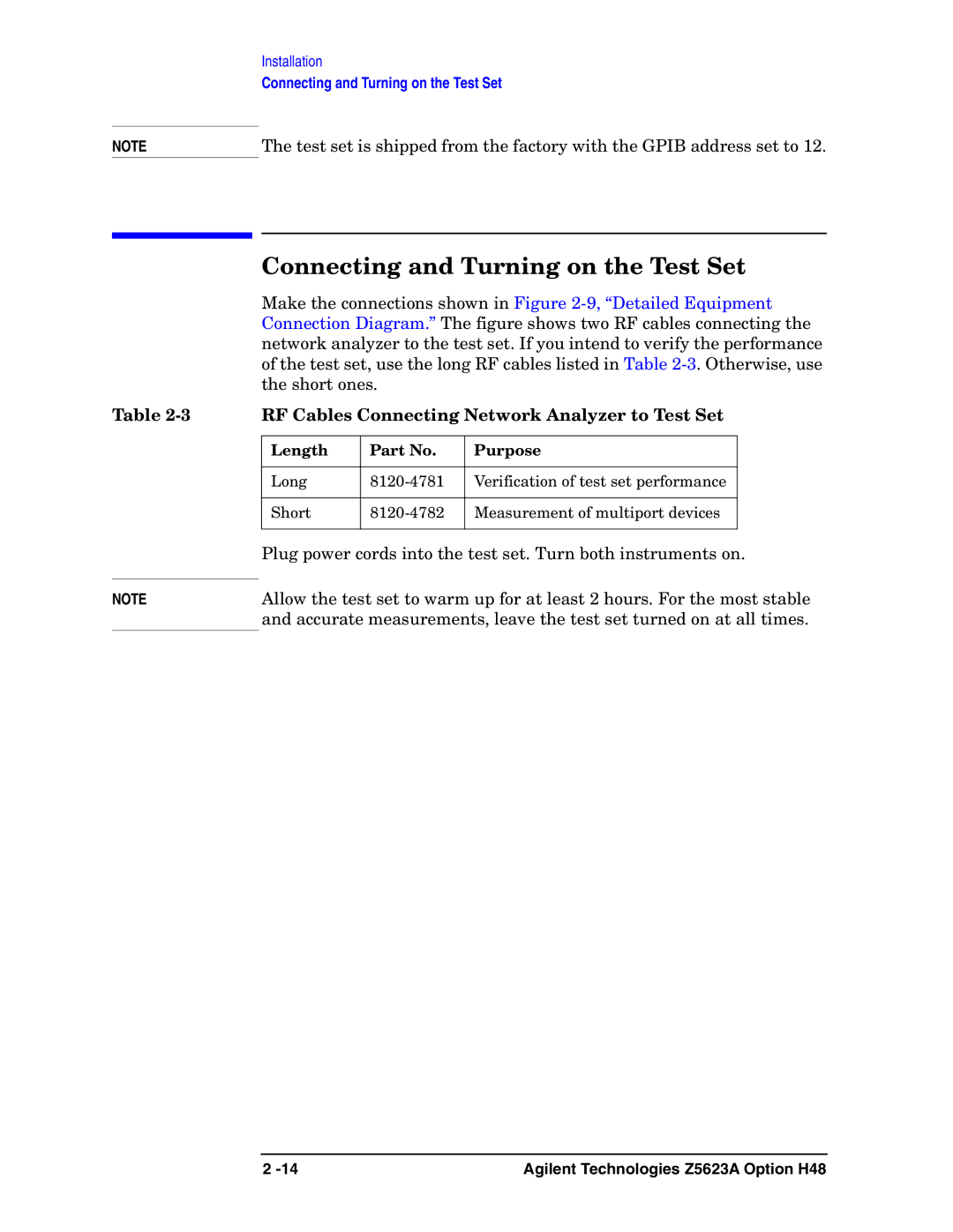
Make the connections shown in Figure
RF Cables Connecting Network Analyzer to Test Set
Length | Part No. | Purpose |
|
|
|
Long | Verification of test set performance | |
|
|
|
Short | Measurement of multiport devices | |
|
|
|
Plug power cords into the test set. Turn both instruments on.
Allow the test set to warm up for at least 2 hours. For the most stable and accurate measurements, leave the test set turned on at all times.
2 | Agilent Technologies Z5623A Option H48 |
