Installation
Connecting and Turning on the Test Set
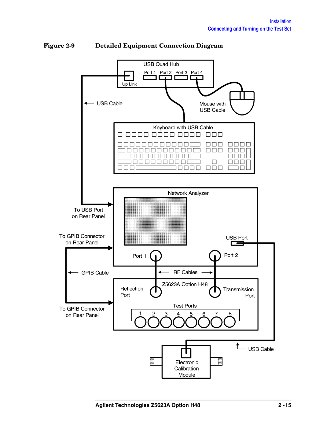
Figure 2-9 Detailed Equipment Connection Diagram
|
| USB Quad Hub |
|
|
|
| |||
|
| Port 1 | Port 2 | Port 3 | Port 4 |
|
| ||
| Up Link |
|
|
|
|
|
|
| |
USB Cable |
|
|
|
| Mouse with | ||||
|
|
|
|
|
| USB Cable | |||
|
| Keyboard with USB Cable |
|
| |||||
|
|
| Network Analyzer |
|
| ||||
To USB Port |
|
|
|
|
|
|
|
| |
on Rear Panel |
|
|
|
|
|
|
|
| |
To GPIB Connector |
|
|
|
|
|
|
| USB Port | |
on Rear Panel |
|
|
|
|
|
|
|
| |
| Port 1 |
|
|
|
|
| Port 2 | ||
GPIB Cable |
|
|
| RF Cables |
|
|
| ||
| Reflection |
| Z5623A Option H48 |
| Transmission | ||||
|
|
|
|
|
|
| |||
| Port |
|
|
|
|
|
| Port | |
To GPIB Connector |
|
|
| Test Ports |
|
|
| ||
1 | 2 | 3 | 4 | 5 | 6 | 7 | 8 | ||
on Rear Panel | |||||||||
Electronic
Calibration
Module
![]() USB Cable
USB Cable
Agilent Technologies Z5623A Option H48 | 2 |
