Calibrating the Network Analyzer
Performing the Calibration
Performing the Calibration
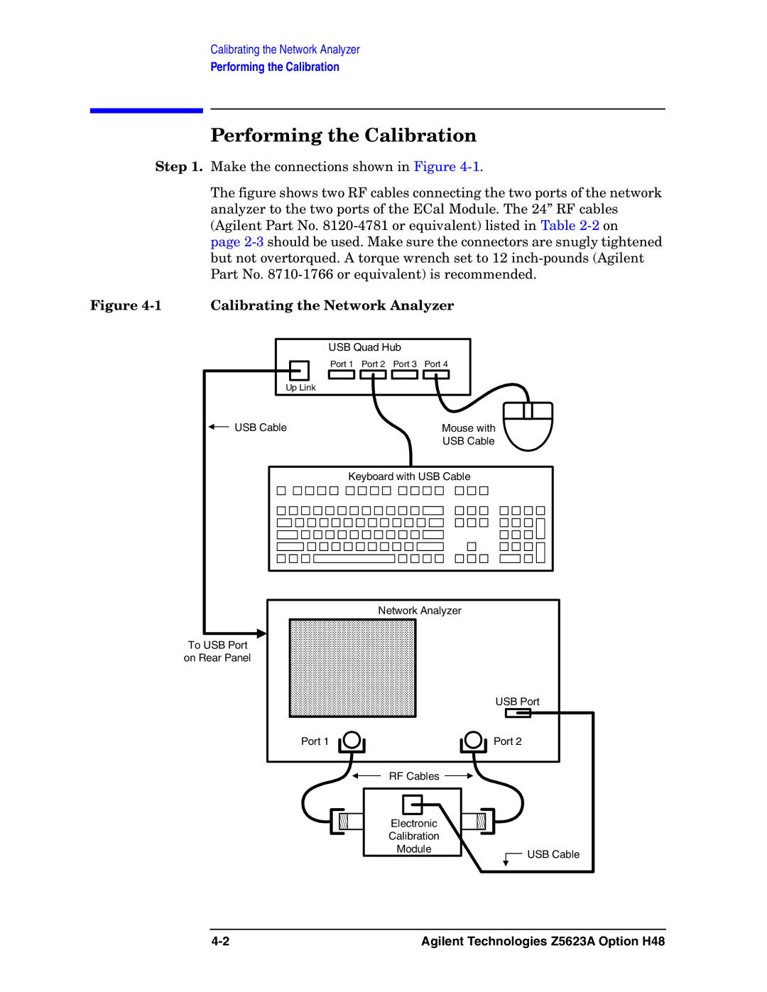
Step 1. Make the connections shown in Figure
The figure shows two RF cables connecting the two ports of the network analyzer to the two ports of the ECal Module. The 24” RF cables (Agilent Part No. 8120-4781 or equivalent) listed in Table 2-2 on page 2-3 should be used. Make sure the connectors are snugly tightened but not overtorqued. A torque wrench set to 12 inch-pounds (Agilent Part No. 8710-1766 or equivalent) is recommended.
Figure 4-1 Calibrating the Network Analyzer
USB Quad Hub |
| |
Port 1 | Port 2 Port 3 | Port 4 |
Up Link |
|
|
USB Cable |
| Mouse with |
|
| USB Cable |
Keyboard with USB Cable | ||
| Network Analyzer | |
To USB Port |
|
|
on Rear Panel |
|
|
USB Port
Port 1 | Port 2 |
RF Cables ![]()
Electronic
Calibration
Module![]() USB Cable
USB Cable
Agilent Technologies Z5623A Option H48 |