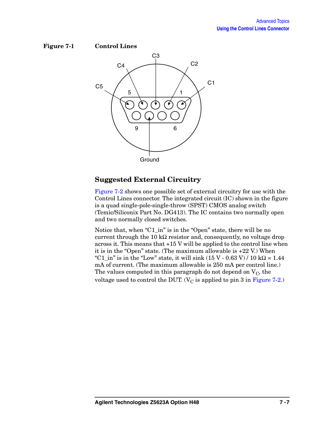
Figure | Control Lines |
C4
C5
5
9
Advanced Topics
Using the Control Lines Connector
C3
C2
C1
1
6
Ground
Suggested External Circuitry
Figure 7-2 shows one possible set of external circuitry for use with the Control Lines connector. The integrated circuit (IC) shown in the figure is a quad single-pole-single-throw (SPST) CMOS analog switch (Temic/Siliconix Part No. DG413). The IC contains two normally open and two normally closed switches.
Notice that, when “C1_in” is in the “Open” state, there will be no current through the 10 kΩ resistor and, consequently, no voltage drop across it. This means that +15 V will be applied to the control line when it is in the “Open” state. (The maximum allowable is +22 V.) When “C1_in” is in the “Low” state, it will sink (15 V - 0.63 V) / 10 kΩ = 1.44 mA of current. (The maximum allowable is 250 mA per control line.) The values computed in this paragraph do not depend on VC, the voltage used to control the DUT. (VC is applied to pin 3 in Figure
Agilent Technologies Z5623A Option H48 | 7 |