Performance Verification
Verifying Crosstalk Specs
Verifying Crosstalk Specs
Crosstalk need only be measured on adjacent ports. Two 50 Ω shorts are required for this test.
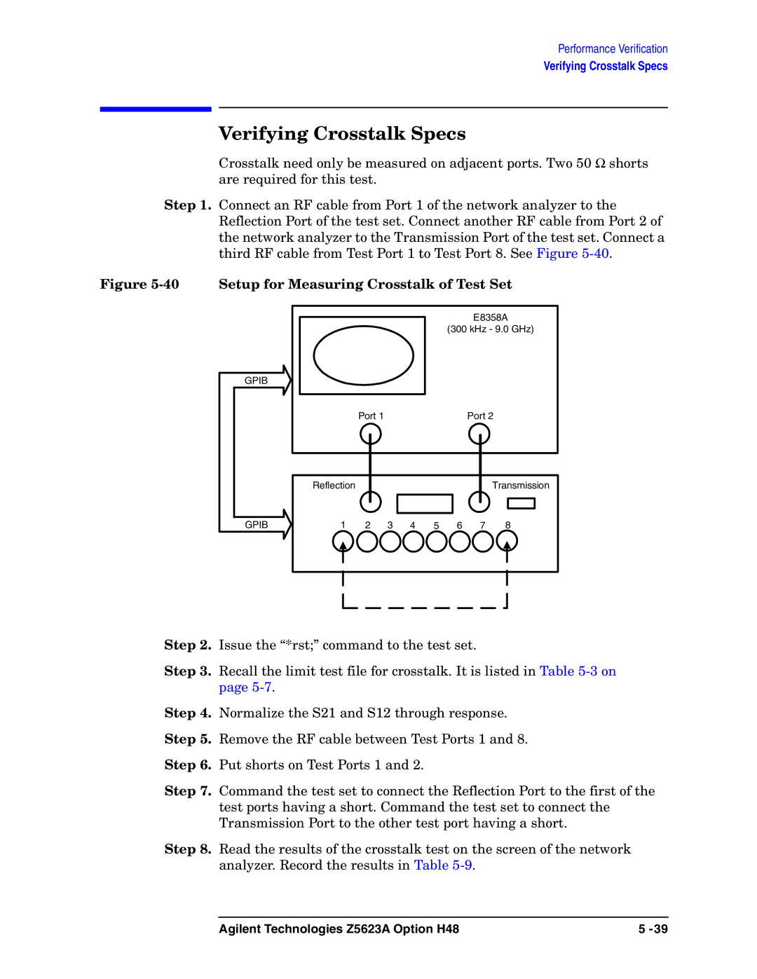
Step 1. Connect an RF cable from Port 1 of the network analyzer to the Reflection Port of the test set. Connect another RF cable from Port 2 of the network analyzer to the Transmission Port of the test set. Connect a third RF cable from Test Port 1 to Test Port 8. See Figure
Figure 5-40 Setup for Measuring Crosstalk of Test Set
E8358A
(300 kHz - 9.0 GHz)
GPIB
Port 1 | Port 2 |
Reflection
Transmission
GPIB
1 | 2 | 3 | 4 | 5 | 6 | 7 | 8 |
Step 2. Issue the “*rst;” command to the test set.
Step 3. Recall the limit test file for crosstalk. It is listed in Table
Step 4. Normalize the S21 and S12 through response.
Step 5. Remove the RF cable between Test Ports 1 and 8.
Step 6. Put shorts on Test Ports 1 and 2.
Step 7. Command the test set to connect the Reflection Port to the first of the test ports having a short. Command the test set to connect the Transmission Port to the other test port having a short.
Step 8. Read the results of the crosstalk test on the screen of the network analyzer. Record the results in Table
Agilent Technologies Z5623A Option H48 | 5 |