Advanced Topics
Using the Control Lines Connector
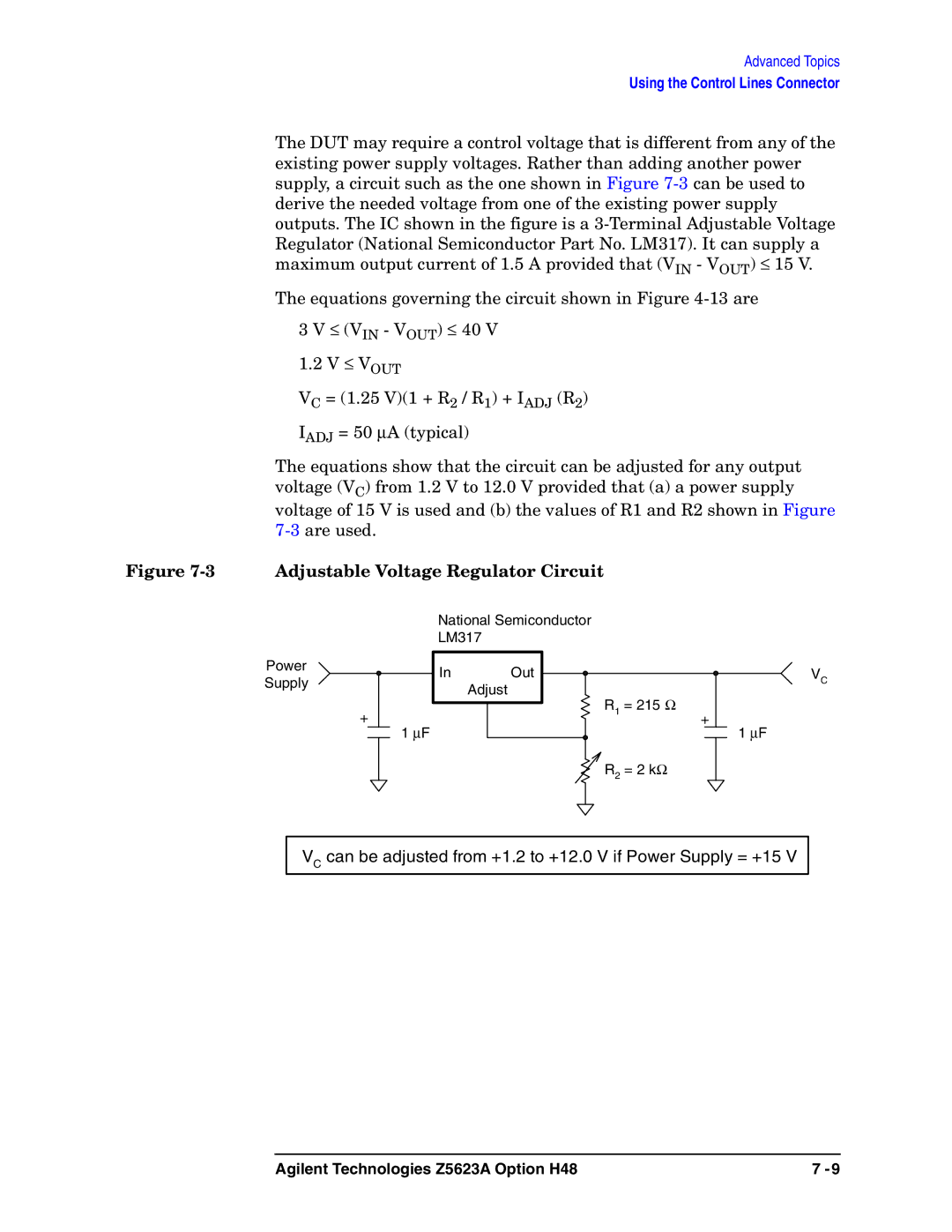
The DUT may require a control voltage that is different from any of the existing power supply voltages. Rather than adding another power supply, a circuit such as the one shown in Figure
The equations governing the circuit shown in Figure
3V ≤ (VIN - VOUT) ≤ 40 V 1.2 V ≤ VOUT
VC = (1.25 V)(1 + R2 / R1) + IADJ (R2)
IADJ = 50 ∝A (typical)
The equations show that the circuit can be adjusted for any output voltage (VC) from 1.2 V to 12.0 V provided that (a) a power supply voltage of 15 V is used and (b) the values of R1 and R2 shown in Figure
Figure 7-3 Adjustable Voltage Regulator Circuit
National Semiconductor
LM317
Power
Supply
+
In Out
Adjust
1 ∝F
R1 = 215 Ω
![]() R2 = 2 kΩ
R2 = 2 kΩ
+
VC
1∝F
VC can be adjusted from +1.2 to +12.0 V if Power Supply = +15 V
Agilent Technologies Z5623A Option H48 | 7 |