Contents
HPIIISi Twinax Card
FCC Statement
HPIIISi Twinax Card
NOM Statement
Trademarks Used in this Manual
Contents
100
Specifications
System Hardware Required
Processor
General Overview
Introduction
Unpacking
Quick Start
Quick Start
Sample page of the Twinax Card’s self-test
Installation
Host System Emulation Device ID
Putting the Card into the Printer
Connecting to the Host
Connecting to a PC
Configuration
Printer Front-Panel Setup
Host/PC-Download Commands
Zxx,y/Zxx,yy/Zxx,yyyC
Commands In Detail
Command 02, Alternate CPT-End Delimiter
Possible Results Arguments
Possible Results cont’d Arg’s cont’d France
APO OFF
Command 10, Line Spacing
Command 13, Paper Drawer
Command 15, Paper Drawer
Command 17, Character Set
Command 19, Starting Horizontal Position
Possible Arguments Results
Possible Results Arguments OFF no duplexing
Possible Results Arguments OFF normal printing
Command 50, Sharing-Port Timeout
Command 98, Restore Defaults or Print Configuration
Command 99, Save All Current Settings
Restoring the Factory Defaults
Parallel-Port Initialization
Operation
PC/LAN Printing
Host-Port Initialization
Host Printing
Typestyle Font ID Pitch Number Hex
Typeface
Using Fonts in Data Processing
Formatting
Printing on 11 X 17 and A3 Size Paper
Drawer
Value
Rotation
Printing with Computer Output Reduction
Print-Orientation Settings
COR CPI Reduction
Data processing
Word processing
Viewing and Changing PAGE-ROTATION Settings
Envelope Printing
Operation
Duplex Printing
Other Print Commands
Other Print Commands
Command Function
Advanced Features
Command Pass-Through
User-Defined Command Strings
User-Defined Fonts
Color Printing
Printing Bar Codes
Printable Bar Codes
Width
Module Width in mm Inches
Chkd
BAR-CODE Notes
0123456789
UPC a
5670
Code
Character Subsets of Code
Character Subsets of Code
NUL SOH STX ETX EOT ENQ ACK BEL DLE DC1 DC2 DC3
DC4 NAK SYN
Card’s Proprietary Graphics Language
Card’s Graphics Language Commands
Card’s Graphics Language Parameters
Advanced Features
HPIIISi Twinax Card
X,Y-Coordinate System on
100,600
Inches
Line width = 2mm
30% shading
Center
180 Center Start 900,900 500,900
HPIIISi Twinax Card
Oclock = starting point for first pie segment
14. a three-segment pie chart
15. Bar chart histogram
HPIIISi Twinax Card
Start
Text
Start
Graphics Language in Action
18. Finished bar chart
Inches Approximate Area Bar Chart
Inch Inches Origin of Chart
Bar Chart-Boyd
Bar Chart-Gary
Bar Chart-Shawn
¬GT50015000SALES Calls PER DAY
Linking Graphical Output to a Host Application
Printing Images from the Host
Advanced Features
Twisted-Pair Applications
Troubleshooting
Card’s Self-Test
Troubleshooting
Ebcdic Hex Dump
Ascii Hex Dump
Self-Diagnostics
Card’s jumpers
Test Sequence Complete
Problem or Message Probable Cause Action
Problem-Resolution Guide
See Section
105
Calling Your Supplier
Shipping and Packaging
Appendix a Font Reference
Typeface Symbol Orient Pitch Point Font/ID Resident Fonts
Resident Scalable Fonts
Typeface Symbol Orient Pitch Point Font/ID
109
110
ProCollection Cartridge
112
WordPerfect Cartridge
Microsoft Cartridge
Cartridge
Forms, Etc. Cartridge
Text Equations Cartridge
Global Text Cartridge
118
Appendix B Character Sets
Figure B-1. Code Page 850 Character Set
Figure B-2. Roman 8 Character Set
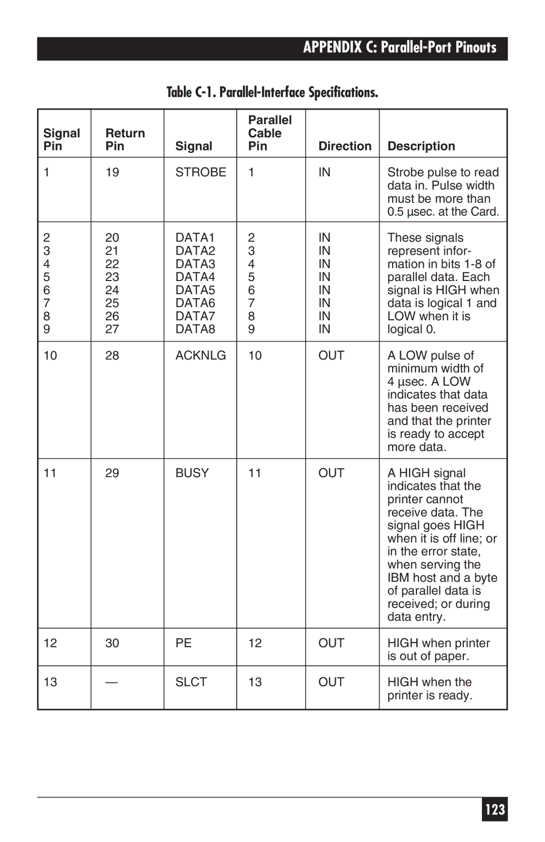
Appendix C Parallel-Port Pinouts
Parallel Signal Return Cable Pin Direction Description
Appendix C Parallel-Port Pinouts
Table C-1 . Parallel-Interface Specifications
Appendix D HP MIO Resident Scalable Font Numbers
Font Font ID No
126
Appendix E Transferring Power to Pin
128
Copyright 1998. Black Box Corporation. All rights reserved