Contents
Controls, Start-Up, Operation, Service and Troubleshooting
Safety Considerations
Contents
Sents pressing Enter to move into the next level
General
Basic Control Usage
Series Product Line
Scrolling Marquee
System Pilot User Interface
Test
START-UP
Fan Performance 48AJ,AK027,030 and 48A2,A3025-030 Units
Fan Performance 48AJ,AK020,025 and 48A2,A3020 Units
Fan Performance 48AJ,AK036 Units
Fan Performance 48AJ,AK,A2,A3035 Units
Fan Performance 48AJ,AK041 Units
Fan Performance 48AJ,AK,A2,A3040 Units
Fan Performance 48AJ,AK051 Units
Fan Performance 48AJ,AK,A2,A3050 Units
Fan Performance 50AJ,AK020,025 and 50A2,A3020 Units
Fan Performance 48AJ,AK,A2,A3060 Units
Fan Performance 50AJ,AKA2,A3035 Units
Fan Performance 50AJ,AK027,030 and 50A2,A3025-030 Units
Fan Performance 50AJ,AK,A2,A3040 Units
Fan Performance 50AJ,AK036 Units
Fan Performance 50AJ,AK,A2,A3050 Units
Fan Performance 50AJ,AK041 Units
Fan Performance 50AJ,AK,A2,A3060 Units
Fan Performance 50AJ,AK051 Units
Fan Performance 48AW,AY027,030 and 48A4,A5025-030 Units
Fan Performance 48AW,AY020,025 and 48A4,A5020 Units
Fan Performance 48AW,AY036 Units
Fan Performance 48AW,AY,A4,A5035 Units
Fan Performance 48AW,AY041 Units
Fan Performance 48AW,AY,A4,A5040 Units
Fan Performance 48AW,AY051 Units
Fan Performance 48AW,AY,A4,A5050 Units
Fan Performance 50AW,AY020,025 and 50A4,A5020 Units
Fan Performance 48AW,AY,A4,A5060 Units
Fan Performance 50AW,AY,A4,A5035 Units
Fan Performance 50AW,AY027,030 and 50A4,A5025-030 Units
Fan Performance 50AW,AY,A4,A5040 Units
Fan Performance 50AW,AY036 Units
Fan Performance 50AW,AY,A4,A5050 Units
Fan Performance 50AW,AY041 Units
Fan Performance 50AW,AY,A4,A5060 Units
Fan Performance 50AW,AY051 Units
Air Quantity Limits 48AJ,AK,AW,AY,A2,A3,A4,A5
Motor Limitations
Air Quantity Limits 50AJ,AK,AW,AY,A2,A3,A4,A5
Controls Quick Start
Page
Indoor Air Quality IAQ Options
Service Test
MLV
Service Test
Demand Controlled Ventilation Control
Third Party Control
Controls Operation
Expansion Range CCN Point
Operating Modes Display Table
Hvac
TYP = 6 SPT-2 STG
TYP = 3 TSTAT-MULTI
Expansion Range Units CCN Point Defaults
Unit Configuration
There will be no MAT calculation
Under Configuration→UNIT
Supply Air Reset Configuration
Machine Dependent Configurations
Setpoints
Cooling Configuration
Are VAV occupied cooling offsets under Setpoints
Advanced Scroll Temperature Protection Label
Cool Mode Evaluation
LV.T
Cool/Heat Set Point Offsets Configuration
Stage Sequence 48/50AJ,AW030-060
Stage Sequence 48/50AJ,AW020-027
Stage Sequence
Stage Sequence 48/50A2,A4020-027
Staging Sequence with Hot Gas Bypass 48/50AK,AY030-060
Stage Sequence 48/50A2,A4030-060
Staging Sequence with Hot Gas Bypass 48/50A3,A5030-060
PCT = MAT EDT/ C.CAP
Run Status Mode Trip Helper
Expansion Range Units CCN Point Write Status
Run Status Cool Display
Inputs→GEN.I→DL.S1 Inputs→GEN.I→DL.S2
Control will not attempt to learn MAT over time
Expansion Range Units CCN Point Default
Demand Limit Configuration
FAN Relay 48/50A Unit Size
Condenser Fan Staging
Occupied Heating Enable OC.EN This configuration
Heating Configuration
Uhsp
Expansion Range Units CCN Default Point Ohsp
Expansion Units CCN Point
Mode Trip Helper Table
Unit Model no
Staged Gas Configuration
Staged Gas Heat 48AJ,AK,AW,AY Units
Unit Size
Relay Output Stage
Staged Gas Heat 48A2,A3,A4,A5 Units
Capacity
IGC LED Indicators
Hvac mode = Tempering Vent
LED Indication Error Code
Page
Static Pressure Control Configuration
As an example, the static pressure reset limit SP.LM =
Fan Status Monitoring
Fan Status Monitoring Configuration
Static Pressure Reset Related Points
Dirty Filter Switch Points
Outdoor Enthalpy Changeover
None
Custom Changeover Curve Example
Economizer Configuration Table
SPT Multi-Staging
Tstat 2 Stage
SPT 2 Stage
Economizer Run Status Table
Power Exhaust Staging BP.CF =
Building Pressure Configuration
PE.A PE.B PE.C
Expansion Range CCN Write Point Status
PID
Indoor Air Quality Control The indoor air quality
IQ.A.F = 2 Fan On Occupied/Unoccupied IAQ
Described above when DAQ is above the DAQ Fan On Set
Will be turned off when DAQ is below the DAQ Fan Off Set
Trol can also be set up to respond to a discrete IAQ input
IAQ Purge Configuration → IAQ → IAQ.P → IQ.PG
Dehumidification Configuration
Indoor Air Quality Configuration
Carrier Comfort Network CCN System It
Temperature Compensated Start This logic is
Expansion Range Units CCN Point
Expansion Range Units Point Default
CCN Configuration
Sensor Trim Configuration
Alert Limit Configuration
Discrete Switch Logic Configuration The SW.LG
Remote Switch Configuration
Time Clock Configuration
Switch Logic Configuration
Display Configuration
Open
Remote Switch Logic Configuration
Closed
Time Clock Configuration
Troubleshooting
Compressor Cycles on LOW Pressure
Cooling Service Analysis
Problem Solution Compressor does not RUN
Compressor Stops on High Pressure
Frosted Suction Line
Unit Operates TOO Long or Continuously
System is Noisy
Compressor Loses OIL
Electric Heat Service Analysis
Gas Heating Service Analysis
Problem Cause Remedy
IGC Service Analysis Logic
5K Thermistor Temperature vs. Resistance SCT Sensors English
5K Thermistor Temperature vs. Resistance SCT Sensors SI
143
Pressure Voltage Psig Drop
Pressure Voltage Psig
Pressure Voltage Psig Drop
175
503
PCT = MAT EDT/C.CAP
Economizer Run Status Display Table
Auto View of Run Status Display Table
Expansion Range Units Point Write Status
Compressor Run Hours Display Table
Mode Trip Helper Display Table
Cooling Information Display Table
CCN/Linkage Display Table
Expansion Range Units Point Write Status Vers
Time Guard Display Table
Software Version Numbers Display Table
Expansion Range Units Point Write Status Tmgd
P051
Alert and Alarm Codes
CEM
Check for welded contactor Verify CS wiring
T122 Circuit a High Saturated Suction Temperature
Page
Page
At Configuration→UNIT→SENS→FLT.S
Major System Components
Factory-Installed Components
102
103
104
105
Typical Auxiliary Control Box Wiring Schematic
106
~~~ ~~~~
107
108
109
110
111
112
113
Typical Power Schematic 48/50A2,A3,A4,A5060 Unit Shown
114
Typical Controls Option Wiring Schematic
Typical Small Chassis Component Location Size 020-035 Units
115
Typical Large Chassis Component Locations Size 036-060 Units
116
117
118
Main Control Board MBB Inputs and Outputs
119
Economizer Control Board ECB1 Inputs and Outputs
120
VAV Control Board ECB2 Inputs and Outputs
Outputs Sfanvfd
121
Staged Gas Control Board SCB Inputs and Outputs
IGC Board Inputs and Outputs
Controls Expansion Board CEM Inputs
122
Terminal Function
123
124
W2 G
Board SW1 SW2 SW3 SW4 ECB1 ECB2 SCB CEM
125
Field Connection Terminal Strips
IME
126
CID
127
Hvac
128
Service
Gas Heat Section Details
Manufacturer Lubricant
Lubrication
131
Evaporator Fan Service and Replacement
Belt Tension Adjustment To adjust belt tension
Evaporator-Fan Motor Replacement
Unit Refrigerant Size Liquid
Condenser-Fan Adjustment
Round Tube, Plate Fin Unit Charge
132
133
Charging Chart 48/50A2,A3,A4,A5020 with R-410A Refrigerant
134
27 Ton Mchx Circuit a Charging Chart
135
Charging Chart 48/50A2,A3,A4,A5030 with R-410A Refrigerant
136
Charging Chart 48/50A2,A3,A4,A5035 with R-410A Refrigerant
Charging Chart 48/50A2,A3,A4,A5050 with R-410A Refrigerant
Charging Chart 48/50A2,A3,A4,A5040 with R-410A Refrigerant
138
Charging Chart 48/50A2,A3,A4,A5060 with R-410A Refrigerant
Main Burner Removal
Gas Valve Part Number EF33CW271
140
Mode RUN Status
141
Appendix a Local Display Tables
142
Description Range Units CCN Point Default
143
Mode Inputs
144
Mode Configuration
→BP.SP
145
→SC.OV→SPT.O
146
147
Mode Time Clock
148
Appendix B CCN Tables
Status Display Tables
Appendix B CCN Tables
149
Uinputs
150
Display Name Range Units Point Name Write Status Temps
Tstat
151
152
Config Tables
Name Range Units Point Name Default Schedovr
Name Range Units Point Name Default Allm
153
SERVICE-CONFIG Tables
154
Name Range Units Point Name Default Heat
Trim
155
Name Range Units Point Name Default Swlg
Dmandlim
Display Name Range Units Point Name Write Status ALARMS01
ALARMS02 ALARMS03 ALARMS04 ALARMS05 Compresr
156
Ecdiag
Maintenance Display Tables
157
Display Name Range Units Point Name Write Status Econmin
158
159
160
Table a VFD Terminal Designations
Appendix C VFD Information
161
Appendix C VFD Information
Table B VFD Configurations
Over Ride
Fig. C Standard Display Example
Appendix C VFD Information
Appendix C VFD Information
166
Table C Fault Codes
167
Table D Alarm Codes
Replace the cooling fan Restore power
Table E Maintenance Intervals
Fig. D Main Fan Replacement Frame Sizes R1-R4
169
Fig. F Internal Enclosure Fan Replacement
Appendix D Mode Selection Process
171
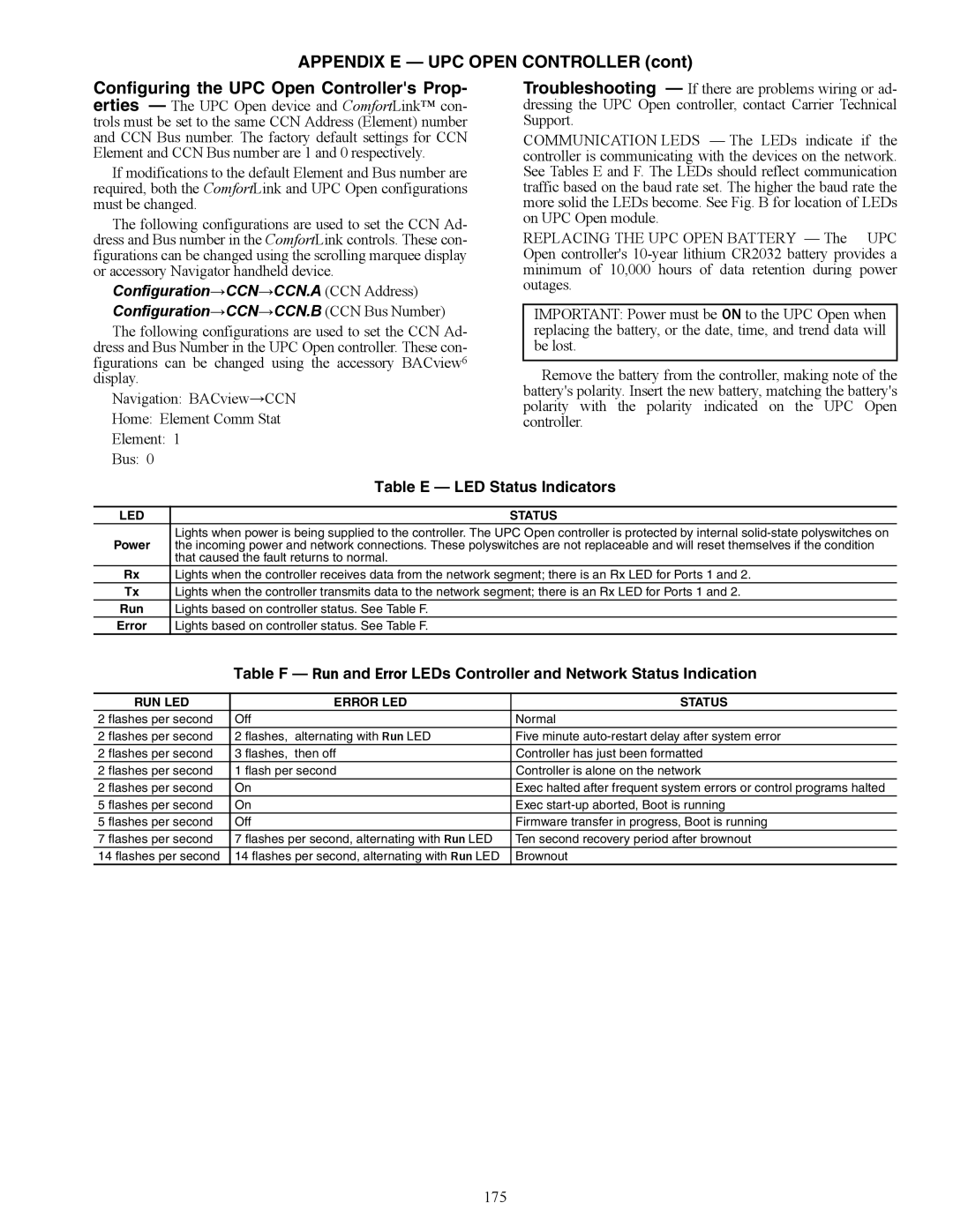
Appendix E UPC Open Controller
DS8 DS7 DS6 DS5 DS4 DS3
Table a SW3 Protocol Switch Settings For MS/TP
Table B Baud Selection Table
172
Appendix E UPC Open Controller
Table C MS/TP Wiring Recommendations
173
CMP
Wiring Specifications Recommended Vendors and Part Numbers
174
Rmcorp
LED Status
Table E LED Status Indicators
RUN LED Error LED Status
175
Object Name Point
Bacnet Point Name Read Units Default Range Object ID
Network Points List
176
177
Appendix E UPC Open Controller Network Points List
178
179
Bacnet Point Name Read Units Default Range Object ID Only
180
181
182
183
Index
Copyright 2010 Carrier Corporation
Expansion Range Default Entry
Controls SET Point and Configuration LOG
CL-2
CL-3
CL-4
CL-5
PRE-START-UP
Unit START-UP Checklist