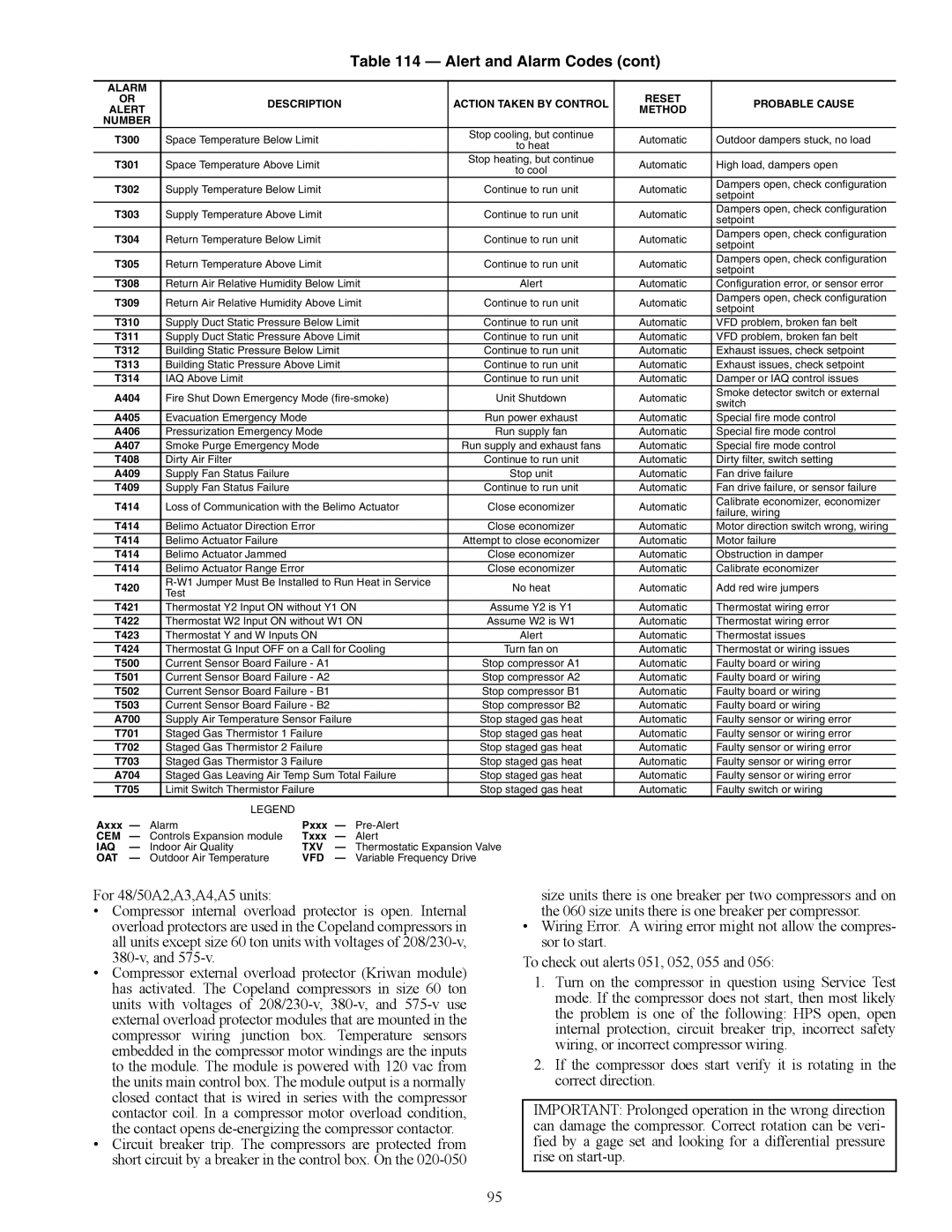
Table 114 — Alert and Alarm Codes (cont)
ALARM |
|
|
|
|
|
|
|
| |
OR |
| DESCRIPTION |
| ACTION TAKEN BY CONTROL | RESET | PROBABLE CAUSE | |||
ALERT |
|
| METHOD | ||||||
|
|
|
|
|
|
| |||
NUMBER |
|
|
|
|
|
|
| ||
T300 |
| Space Temperature Below Limit |
|
| Stop cooling, but continue | Automatic | Outdoor dampers stuck, no load | ||
|
|
| to heat | ||||||
|
|
|
|
|
|
|
|
| |
T301 |
| Space Temperature Above Limit |
|
| Stop heating, but continue | Automatic | High load, dampers open | ||
|
|
| to cool | ||||||
|
|
|
|
|
|
|
|
| |
T302 |
| Supply Temperature Below Limit |
|
| Continue to run unit | Automatic | Dampers open, check configuration | ||
|
|
| setpoint | ||||||
|
|
|
|
|
|
|
|
| |
T303 |
| Supply Temperature Above Limit |
|
| Continue to run unit | Automatic | Dampers open, check configuration | ||
|
|
| setpoint | ||||||
|
|
|
|
|
|
|
|
| |
T304 |
| Return Temperature Below Limit |
|
| Continue to run unit | Automatic | Dampers open, check configuration | ||
|
|
| setpoint | ||||||
|
|
|
|
|
|
|
|
| |
T305 |
| Return Temperature Above Limit |
|
| Continue to run unit | Automatic | Dampers open, check configuration | ||
|
|
| setpoint | ||||||
|
|
|
|
|
|
|
|
| |
T308 |
| Return Air Relative Humidity Below Limit | Alert | Automatic | Configuration error, or sensor error | ||||
T309 |
| Return Air Relative Humidity Above Limit | Continue to run unit | Automatic | Dampers open, check configuration | ||||
| setpoint | ||||||||
|
|
|
|
|
|
|
|
| |
T310 |
| Supply Duct Static Pressure Below Limit | Continue to run unit | Automatic | VFD problem, broken fan belt | ||||
T311 |
| Supply Duct Static Pressure Above Limit | Continue to run unit | Automatic | VFD problem, broken fan belt | ||||
T312 |
| Building Static Pressure Below Limit |
| Continue to run unit | Automatic | Exhaust issues, check setpoint | |||
T313 |
| Building Static Pressure Above Limit |
| Continue to run unit | Automatic | Exhaust issues, check setpoint | |||
T314 |
| IAQ Above Limit |
|
|
| Continue to run unit | Automatic | Damper or IAQ control issues | |
A404 |
| Fire Shut Down Emergency Mode | Unit Shutdown | Automatic | Smoke detector switch or external | ||||
| switch | ||||||||
|
|
|
|
|
|
|
|
| |
A405 |
| Evacuation Emergency Mode |
|
| Run power exhaust | Automatic | Special fire mode control | ||
A406 |
| Pressurization Emergency Mode |
|
| Run supply fan | Automatic | Special fire mode control | ||
A407 |
| Smoke Purge Emergency Mode |
|
| Run supply and exhaust fans | Automatic | Special fire mode control | ||
T408 |
| Dirty Air Filter |
|
|
| Continue to run unit | Automatic | Dirty filter, switch setting | |
A409 |
| Supply Fan Status Failure |
|
|
| Stop unit | Automatic | Fan drive failure | |
T409 |
| Supply Fan Status Failure |
|
|
| Continue to run unit | Automatic | Fan drive failure, or sensor failure | |
T414 |
| Loss of Communication with the Belimo Actuator | Close economizer | Automatic | Calibrate economizer, economizer | ||||
| failure, wiring | ||||||||
|
|
|
|
|
|
|
|
| |
T414 |
| Belimo Actuator Direction Error |
|
| Close economizer | Automatic | Motor direction switch wrong, wiring | ||
T414 |
| Belimo Actuator Failure |
|
|
| Attempt to close economizer | Automatic | Motor failure | |
T414 |
| Belimo Actuator Jammed |
|
|
| Close economizer | Automatic | Obstruction in damper | |
T414 |
| Belimo Actuator Range Error |
|
| Close economizer | Automatic | Calibrate economizer | ||
T420 |
| No heat | Automatic | Add red wire jumpers | |||||
| Test |
|
|
| |||||
|
|
|
|
|
|
|
|
| |
T421 |
| Thermostat Y2 Input ON without Y1 ON | Assume Y2 is Y1 | Automatic | Thermostat wiring error | ||||
T422 |
| Thermostat W2 Input ON without W1 ON | Assume W2 is W1 | Automatic | Thermostat wiring error | ||||
T423 |
| Thermostat Y and W Inputs ON |
|
| Alert | Automatic | Thermostat issues | ||
T424 |
| Thermostat G Input OFF on a Call for Cooling | Turn fan on | Automatic | Thermostat or wiring issues | ||||
T500 |
| Current Sensor Board Failure - A1 |
|
| Stop compressor A1 | Automatic | Faulty board or wiring | ||
T501 |
| Current Sensor Board Failure - A2 |
|
| Stop compressor A2 | Automatic | Faulty board or wiring | ||
T502 |
| Current Sensor Board Failure - B1 |
|
| Stop compressor B1 | Automatic | Faulty board or wiring | ||
T503 |
| Current Sensor Board Failure - B2 |
|
| Stop compressor B2 | Automatic | Faulty board or wiring | ||
A700 |
| Supply Air Temperature Sensor Failure |
| Stop staged gas heat | Automatic | Faulty sensor or wiring error | |||
T701 |
| Staged Gas Thermistor 1 Failure |
|
| Stop staged gas heat | Automatic | Faulty sensor or wiring error | ||
T702 |
| Staged Gas Thermistor 2 Failure |
|
| Stop staged gas heat | Automatic | Faulty sensor or wiring error | ||
T703 |
| Staged Gas Thermistor 3 Failure |
|
| Stop staged gas heat | Automatic | Faulty sensor or wiring error | ||
A704 |
| Staged Gas Leaving Air Temp Sum Total Failure | Stop staged gas heat | Automatic | Faulty sensor or wiring error | ||||
T705 |
| Limit Switch Thermistor Failure |
|
| Stop staged gas heat | Automatic | Faulty switch or wiring | ||
|
|
| LEGEND |
|
|
|
|
|
|
Axxx — | Alarm | Pxxx — |
|
|
| ||||
CEM | — | Controls Expansion module | Txxx | — | Alert |
|
|
| |
IAQ | — | Indoor Air Quality | TXV | — | Thermostatic Expansion Valve |
|
| ||
OAT | — | Outdoor Air Temperature | VFD | — | Variable Frequency Drive |
|
| ||
For 48/50A2,A3,A4,A5 units:
•Compressor internal overload protector is open. Internal overload protectors are used in the Copeland compressors in all units except size 60 ton units with voltages of
•Compressor external overload protector (Kriwan module) has activated. The Copeland compressors in size 60 ton units with voltages of
•Circuit breaker trip. The compressors are protected from short circuit by a breaker in the control box. On the
size units there is one breaker per two compressors and on the 060 size units there is one breaker per compressor.
•Wiring Error. A wiring error might not allow the compres- sor to start.
To check out alerts 051, 052, 055 and 056:
1.Turn on the compressor in question using Service Test mode. If the compressor does not start, then most likely the problem is one of the following: HPS open, open internal protection, circuit breaker trip, incorrect safety wiring, or incorrect compressor wiring.
2.If the compressor does start verify it is rotating in the correct direction.
IMPORTANT: Prolonged operation in the wrong direction can damage the compressor. Correct rotation can be veri- fied by a gage set and looking for a differential pressure rise on
95