APPENDIX C — VFD INFORMATION (cont)
4.Use the UP or DOWN keys to highlight the desired parameter and press EDIT (SOFT KEY 2).
5.Use the UP or DOWN keys to change the value of the parameter.
6.Press SAVE (SOFT KEY 2) to store the modified value. Press CANCEL (SOFT KEY 1) to keep the previous val- ue. Any modifications that are not saved will not be changed.
7.Choose another parameter or press EXIT (SOFT KEY 1) to return to the listing of parameter groups. Continue until all the parameters have been configured and then press EXIT (SOFT KEY 1) to return to the main menu.
NOTE: The current parameter value appears above the high- light parameter. To view the default parameter value, press the UP and DOWN keys simultaneously. To restore the default factory settings, select the application macro “HVAC Default.”
VFD Modes — The VFD has several different modes for configuring, operating, and diagnosing the VFD. The modes are:
•Standard Display mode — shows drive status informa- tion and operates the drive
•Parameters mode — edits parameter values individually
•
•Changed Parameters mode — shows all changed parameters
•Drive Parameter Backup mode — stores or uploads the parameters
•Clock Set mode — sets the time and date for the drive
•I/O Settings mode — checks and edits the I/O settings
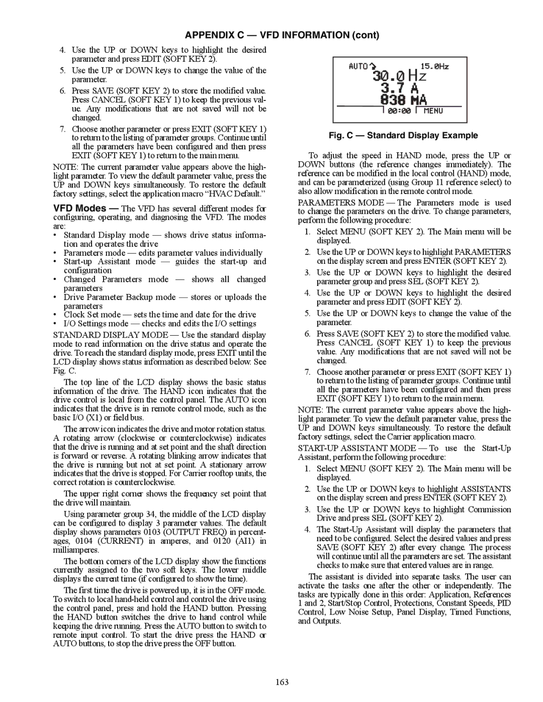
STANDARD DISPLAY MODE — Use the standard display mode to read information on the drive status and operate the drive. To reach the standard display mode, press EXIT until the LCD display shows status information as described below. See Fig. C.
The top line of the LCD display shows the basic status information of the drive. The HAND icon indicates that the drive control is local from the control panel. The AUTO icon indicates that the drive is in remote control mode, such as the basic I/O (X1) or field bus.
The arrow icon indicates the drive and motor rotation status. A rotating arrow (clockwise or counterclockwise) indicates that the drive is running and at set point and the shaft direction is forward or reverse. A rotating blinking arrow indicates that the drive is running but not at set point. A stationary arrow indicates that the drive is stopped. For Carrier rooftop units, the correct rotation is counterclockwise.
The upper right corner shows the frequency set point that the drive will maintain.
Using parameter group 34, the middle of the LCD display can be configured to display 3 parameter values. The default display shows parameters 0103 (OUTPUT FREQ) in percent- ages, 0104 (CURRENT) in amperes, and 0120 (AI1) in milliamperes.
The bottom corners of the LCD display show the functions currently assigned to the two soft keys. The lower middle displays the current time (if configured to show the time).
The first time the drive is powered up, it is in the OFF mode. To switch to local
Fig. C — Standard Display Example
To adjust the speed in HAND mode, press the UP or DOWN buttons (the reference changes immediately). The reference can be modified in the local control (HAND) mode, and can be parameterized (using Group 11 reference select) to also allow modification in the remote control mode.
PARAMETERS MODE — The Parameters mode is used to change the parameters on the drive. To change parameters, perform the following procedure:
1.Select MENU (SOFT KEY 2). The Main menu will be displayed.
2.Use the UP or DOWN keys to highlight PARAMETERS on the display screen and press ENTER (SOFT KEY 2).
3.Use the UP or DOWN keys to highlight the desired parameter group and press SEL (SOFT KEY 2).
4.Use the UP or DOWN keys to highlight the desired parameter and press EDIT (SOFT KEY 2).
5.Use the UP or DOWN keys to change the value of the parameter.
6.Press SAVE (SOFT KEY 2) to store the modified value. Press CANCEL (SOFT KEY 1) to keep the previous value. Any modifications that are not saved will not be changed.
7.Choose another parameter or press EXIT (SOFT KEY 1) to return to the listing of parameter groups. Continue until all the parameters have been configured and then press EXIT (SOFT KEY 1) to return to the main menu.
NOTE: The current parameter value appears above the high- light parameter. To view the default parameter value, press the UP and DOWN keys simultaneously. To restore the default factory settings, select the Carrier application macro.
1.Select MENU (SOFT KEY 2). The Main menu will be displayed.
2.Use the UP or DOWN keys to highlight ASSISTANTS on the display screen and press ENTER (SOFT KEY 2).
3.Use the UP or DOWN keys to highlight Commission Drive and press SEL (SOFT KEY 2).
4.The
The assistant is divided into separate tasks. The user can activate the tasks one after the other or independently. The tasks are typically done in this order: Application, References 1 and 2, Start/Stop Control, Protections, Constant Speeds, PID Control, Low Noise Setup, Panel Display, Timed Functions, and Outputs.
163