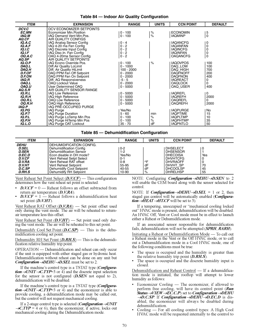
Table 84 — Indoor Air Quality Configuration
ITEM | EXPANSION |
|
| RANGE |
| UNITS |
| CCN POINT |
| DEFAULT |
DCV.C | DCV ECONOMIZER SETPOINTS |
|
|
|
|
|
|
|
|
|
EC.MN | Economizer Min.Position |
| 0 | - 100 |
| % |
| ECONOMIN |
| 5 |
|
|
|
| |||||||
IAQ.M | IAQ Demand Vent Min.Pos. |
| 0 | - 100 |
| % |
| IAQMINP |
| 0 |
AQ.CF | AIR QUALITY CONFIGS |
|
|
|
|
|
|
|
|
|
IQ.A.C | IAQ Analog Sensor Config |
| 0 | - 4 |
|
|
| IAQANCFG |
| 0 |
|
|
|
|
| ||||||
IQ.A.F | IAQ |
| 0 | - 2 |
|
|
| IAQANFAN |
| 0 |
IQ.I.C | IAQ Discrete Input Config |
| 0 | - 2 |
|
|
| IAQINCFG |
| 0 |
IQ.I.F | IAQ Disc.In. Fan Config |
| 0 | - 2 |
|
|
| IAQINFAN |
| 0 |
OQ.A.C | OAQ |
| 0 | - 2 |
|
|
| OAQANCFG |
| 0 |
AQ.SP | AIR QUALITY SETPOINTS |
|
|
|
|
|
|
|
|
|
IQ.O.P | IAQ Econo Override Pos. |
| 0 | - 100 |
| % |
| IAQOVPOS |
| 100 |
|
|
|
| |||||||
DAQ.L | Diff.Air Quality LoLimit |
| 0 | - 1000 |
|
|
| DAQ_LOW |
| 100 |
DAQ.H | Diff. Air Quality HiLimit |
| 100 - 2000 |
|
|
| DAQ_HIGH |
| 700 | |
D.F.OF | DAQ PPM Fan Off Setpoint |
| 0 | - 2000 |
|
|
| DAQFNOFF |
| 200 |
D.F.ON | DAQ PPM Fan On Setpoint |
| 0 | - 2000 |
|
|
| DAQFNON |
| 400 |
IAQ.R | Diff. AQ Responsiveness |
|
|
|
| IAQREACT |
| 0 | ||
OAQ.L | OAQ Lockout Value |
| 0 | - 2000 |
|
|
| OAQLOCK |
| 0 |
OAQ.U | User Determined OAQ |
| 0 | - 5000 |
|
|
| OAQ_USER |
| 400 |
AQ.S.R | AIR QUALITY SENSOR RANGE |
|
|
|
|
|
|
|
|
|
IQ.R.L | IAQ Low Reference |
| 0 | - 5000 |
|
|
| IAQREFL |
| 0 |
|
|
|
|
| ||||||
IQ.R.H | IAQ High Reference |
| 0 | - 5000 |
|
|
| IAQREFH |
| 2000 |
OQ.R.L | OAQ Low Reference |
| 0 | - 5000 |
|
|
| OAQREFL |
| 0 |
OQ.R.H | OAQ High Reference |
| 0 | - 5000 |
|
|
| OAQREFH |
| 2000 |
IAQ.P | IAQ |
|
|
|
|
|
|
|
|
|
IQ.PG | IAQ Purge |
| Yes/No |
|
|
| IAQPURGE |
| No | |
|
|
|
|
| ||||||
IQ.P.T | IAQ Purge Duration |
| 5 | - 60 |
| min |
| IAQPTIME |
| 15 |
IQ.P.L | IAQ Purge LoTemp Min Pos |
| 0 | - 100 |
| % |
| IAQPLTMP |
| 10 |
IQ.P.H | IAQ Purge HiTemp Min Pos |
| 0 | - 100 |
| % |
| IAQPHTMP |
| 35 |
IQ.L.O | IAQ Purge OAT Lockout |
| 35 - 70 |
| dF |
| IAQPNTLO |
| 50 | |
Table 85 — Dehumidification Configuration
ITEM | EXPANSION |
| RANGE | UNITS | CCN POINT |
| DEFAULT |
DEHU | DEHUMIDIFICATION CONFIG. |
|
|
|
|
|
|
D.SEL | Dehumidification Config |
|
| DHSELECT |
| 0 | |
|
|
| |||||
D.SEN | Dehumidification Sensor |
|
| DHSENSOR |
| 1 | |
D.EC.D | Econ disable in DH mode? |
| Yes/No |
| DHECDISA |
| Yes |
D.V.CF | Vent Reheat Setpt Select |
|
| DHVHTCFG |
| 0 | |
D.V.RA | Vent Reheat RAT offset |
| ^F | DHVRAOFF |
| 0 | |
D.V.HT | Vent Reheat Setpoint |
| dF | DHVHT_SP |
| 70 | |
D.C.SP | Dehumidify Cool Setpoint |
| dF | DHCOOLSP |
| 45 | |
D.RH.S | Dehumidify RH Setpoint |
| % | DHRELHSP |
| 55 |
Vent Reheat Set Point Select (D.V.CF) — This configuration determines how the vent reheat set point is selected.
•D.V.CF = 0 — Reheat follows an offset subtracted from return air temperature (D.V.RA).
•D.V.CF = 1 — Reheat follows a dehumidification heat set point (D.V.HT).
Vent Reheat RAT Offset (D.V.RA) — Set point offset used only during the vent mode. The air will be reheated to return- air temperature less this offset.
Vent Reheat Set Point (D.V.HT) — Set point used only dur- ing the vent mode. The air will be reheated to this set point. Dehumidify Cool Set Point (D.C.SP) — This is the dehu- midification cooling set point.
Dehumidity RH Set Point (D.RH.S) — This is the dehumidi- fication relative humidity trip point.
OPERATION — Dehumidification and reheat can only occur if the unit is equipped with either staged gas or hydronic heat. Dehumidification without reheat can be done on any unit but Configuration→DEHU→D.SEL must be set to 2.
If the machine’s control type is a TSTAT type (Configura- tion→UNIT→C.TYP=3 or 4) and the discrete input selection for the sensor is not configured (D.SEN not equal to 2), dehumidification will be disabled.
If the machine’s control type is a TSTAT type (Configura- tion→UNIT→C.TYP=3 or 4) and the economizer is able to provide cooling, a dehumidification mode may be called out, but the control will not request mechanical cooling.
If a
NOTE: Configuring Configuration→DEHU→D.SEN to 2 will enable the CEM board along with the sensor selected for control.
NOTE: If Configuration→DEHU→D.SEL = 1 or 2, then staged gas control will be automatically enabled (Configura- tion→HEAT→HT.CF will be set to 3).
If a tempering, unoccupied or “mechanical cooling locked out” HVAC mode is present, dehumidification will be disabled. An HVAC Off, Vent or Cool mode must be in effect to launch either a Reheat or Dehumidification mode.
If an associated sensor responsible for dehumidification fails, dehumidification will not be attempted (SPRH, RARH).
Initiating a Reheat or Dehumidification Mode — To call out a Reheat mode in the Vent or the Off HVAC mode, or to call out a Dehumidification mode in a Cool HVAC mode, one of the following conditions must be true:
•The space is occupied and the humidity is greater than the relative humidity trip point (D.RH.S).
•The space is occupied and the discrete humidity input is closed.
Dehumidification and Reheat Control — If a dehumidifica- tion mode is initiated, the rooftop will attempt to lower humidity as follows:
•Economizer Cooling — The economizer, if allowed to perform free cooling, will have its control point (Run Status→VIEW→EC.C.P) set to Configuration→DEHU →D.C.SP. If Configuration→DEHU→D.EC.D is dis- abled, the economizer will always be disabled during dehumidification.
•Cooling — For all cooling control types: A High Cool HVAC mode will be requested internally to the control to
70