Page
Page
Page
Preface
Please Read Prior to Installation for Safety
Page
Table of Contents
Digital Keypad Operation
Fault Code Information
Troubleshooting
Start Up
All Brake Resistors & Brake Units Used in AC Motor Drives
Appendix D CE
Appendix C How to Select the Right AC Motor Drive
Model Explanation
Introduction
Receiving and Inspection
Nameplate Information
Series Number Explanation
Drive Frames
Appearances
Installation Steps
Storage
IntroductionVFD-S Series
This page intentionally left blank
Installation and Wiring
Installation
Ambient Conditions
150mm 6inch
85.0 88.0 74.0 13.0 132.25.21 148.05.83 4411.1
Dimensions
88 .0 3 .4
10 2 4
85 .0 3 .3 10 2 4 74 .0 2 .9
85 .0 3 .3 74 .0 2 .9
Frame S1 VFD007S21B
50 .0 1 .9
12 6 4
67 .8 2 .6 51 .0 2 .0
12 7 5
Frame S2 VFD007S11A
Frame S2 VFD007S11B
67 .8 2 .6
12 9 5
100.0 86.5 173.0 186.0 129.3 16.0
Wiring
Basic Wiring Diagrams
Basic Wiring
NFB
For Vfdxxxsxxe NPN sink mode
For Vfdxxxsxxe PNP source mode
FUSE/NFB
External Wiring
Mains power terminals R/L1, S/L2, T/L3 and L/L1, N/L2
Main Terminals Connections
Control circuit terminals U/T1, V/T2, W/T3
No ground loops
Terminals +2/B1, +1 for connecting DC reactor
Terminals +2/B1, B2 for connecting brake resistor
Grounding terminals
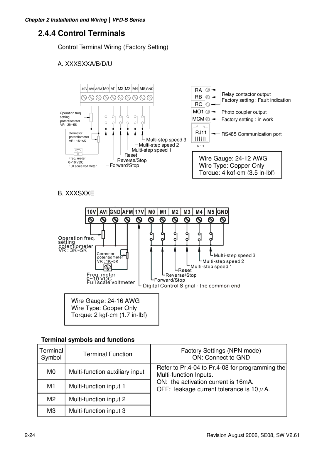
Control Terminals
Terminal symbols and functions
GND
AVI/ACI
General
Digital outputs MO1, MCM
Main Circuit Terminals
Power terminal
AC Input Line Motor Terminal
VFD002S21A/E, VFD004S21A/E, VFD007S21A/E
Power terminal
VFD015S21U/43D/43E/43U, VFD022S21U/23D/43D/43E/43U
VFD015S21D/E, VFD022S21D/E
This page intentionally left blank
Preparations before Start-up
Start Up
Trial Run
Operation Method
Start UpVFD-S Series
This page intentionally left blank
Explanations of Display Messages
Explanation of LED Indicators
Digital Keypad Operation
Description of the Digital Keypad
Digital Keypad OperationVFD-S Series
To shift data
How to Operate the Digital Keypad
This page intentionally left blank
Parameters
Summary of Parameter Settings
Group 0 User Parameters Explanation Settings Factory
Group 1 Basic Parameters Explanation Settings Factory
Explanation Settings Factory
Group 2 Operation Method Parameters Explanation Settings
Setting
Group 3 Output Function Parameters
Group 4 Input Function Parameters Explanation Settings
Forward/reverse N.O. motion
Group 6 Protection Parameters Explanation Settings
Explanation Settings Factory
Group 7 Motor Parameters Explanation Settings Factory
Group 8 Special Parameters Explanation Settings Factory
Group 9 Communication Parameters
Group a PID Parameters Explanation Settings Factory
Explanation Settings Factory
Parameter Settings for Applications
Wire
ParametersVFD-S Series
Running status External system or control wiring
ParametersVFD-S Series
Description of Parameter Settings
Would be displayed as
ParametersVFD-S Series
END
Bit Bit4
Group 1 Basic Parameters
Standard V/F Curve
Factory Setting d10.0
Command
Acceleration/deceleration Characteristics
Group 2 Operation Method Parameters
01Source of Operation Command
115V/230V/460V Series
10kHz
05Loss of ACI Signal 4-20mA
Analog Frequency Meter Analog Current Meter
OFF
TRG
Setting Function Description
Setting Function Description
Example
Group 4 Input Function Parameters
This example shows a potentiometer range of 0 to 5 Volts
Potentiometer Scale
Parameters & Functions table
Max Output Pr.1-00 Freq 60Hz
REV/STOP
Explanations D0 Parameter Disable
D4, d5 External Faults
D6 External Reset
D7, d8, d9 Multi-Step Speed Command
D11 Acceleration/Deceleration Speed Inhibit
D10 Jog Operation Control
D13, d14 External Base Block
D12 First or Second Acceleration/Deceleration Time Selection
D17, d18 PLC Function Control
D15, d16 Increase/Decrease Master Frequency
D19 Counter Trigger
D21 Select ACI / Deselect AVI
D20 Counter Reset
D22 PID function disable
D28 Press UP/DOWN key to switch forward/reverse N.C. motion
09Line Start Lockout
ParametersVFD-S Series
Example 2 Pr.5-07 = d2 Continuously executes program cycles
Example 3 Pr -07 = d3 Execute one cycle step by step
Example 5 Pr -07 = d1 Execute one cycle of the PLC program
Weights =Forward Bit =Reverse
Weights Bit Direction
Group 6 Protection Parameters
Over-voltage Stall Prevention
Factory Setting d150
Present Fault Record
ParametersVFD-S Series
Group 7 Motor Parameters
Group 8 Special Parameters
Output Frequency
Factory Setting d2.0
Maximum Allowable Power Power Loss Time
ParametersVFD-S Series
00Communication Address Settings D1 to d254
+EV
RTU mode
Ascii mode
Stop
LRC CHK
6FH
LRC CHK END1 END0
Starting data address ‘0’ ‘4’ ‘1’
Content Address Functions
Read only
PID error Pld
Exception Meaning Code
Error Meaning Message
Communication program of PC
Group a PID Control
Unit 2 msec
Sleep Function
13 = 56-0X 100100 X 10 =
Over current
Fault Code Information
Common Problems and Solutions
Fault Fault Descriptions Corrective Actions Name
Low voltage
GFF hardware error
OC hardware error
Overheating
Current detection error DC BUS detection error
Fault Descriptions Corrective Actions Name
External Fault
OH error OV error LV error
Reset
Over Current OC
Troubleshooting
Over Voltage OV
Ground Fault
Low Voltage Lv
Overload
Over Heat OH
Keypad Display is Abnormal
Phase Loss PHL
Motor cannot Run
Motor Speed cannot be Changed
Motor does not Run as Expected
Motor Stalls during Acceleration
Environmental Condition
Electromagnetic/Induction Noise
Affecting Other Machines
Serial reactor Phase lead capacitor
Maintenance and Inspections
Daily Inspection
Periodic Inspection
Keypad Maintenance Check Items Methods and Criterion
Voltage Maintenance Check Items Methods and Criterion
Change of copper plate
Check Items Methods and Criterion Period
Year
Change fan To overheating
This page intentionally left blank
Voltage Class 115V Class 230V Class 460V Class
Appendix a Specifications
Appendix a SpecificationsVFD-S Series
All Brake Resistors & Brake Units Used in AC Motor Drives
Appendix B Accessories
Dimensions and Weights for Brake resistors
EMI Filters
Installation
Saddle on both ends Saddle on one end
Length of motor cable
Order P/N RF007S21AA/ RF007S43AA
Order P/N RF022S21BA
Order P/N 08TDT1W4S
Order P/N 12DKT1W3S
Order P/N 35DRT1W3C
Order P/N 22DRT1W3S
~5% impedance
AC Reactor AC Input Reactor Recommended Value
AC Output Reactor Recommended Value
Applications for AC Reactor
Impedance
May be damaged when over current occurs during operation
M1 reactor
Small-capacity
MTE CAT. no
DC Choke Recommended Values
Zero Phase Reactor RF220X00A
Models Screw Size
Din Rail-DR01
Remote Controller RC-01
Conduit Bracket BK-S
Fuse Specification Chart
Non-fuse Circuit Breaker Chart
Related Specification
Appendix C How to Select the Right AC Motor Drive
When one AC motor drive operates one motor
When one AC motor drive operates more than one motor
Capacity Formulas
⋅ IM ≤ the rated current of AC motor drive a
General Precautions
Parameter Settings Note
Selection Note
Standard motor
How to Choose a Suitable Motor
Pole-changing Dahlander motor
Special motors
Motor torque
Power Transmission Mechanism
AC motor drive
Delta ELECTRONICS, INC
Appendix D CE
Delta ELECTRONICS, INC