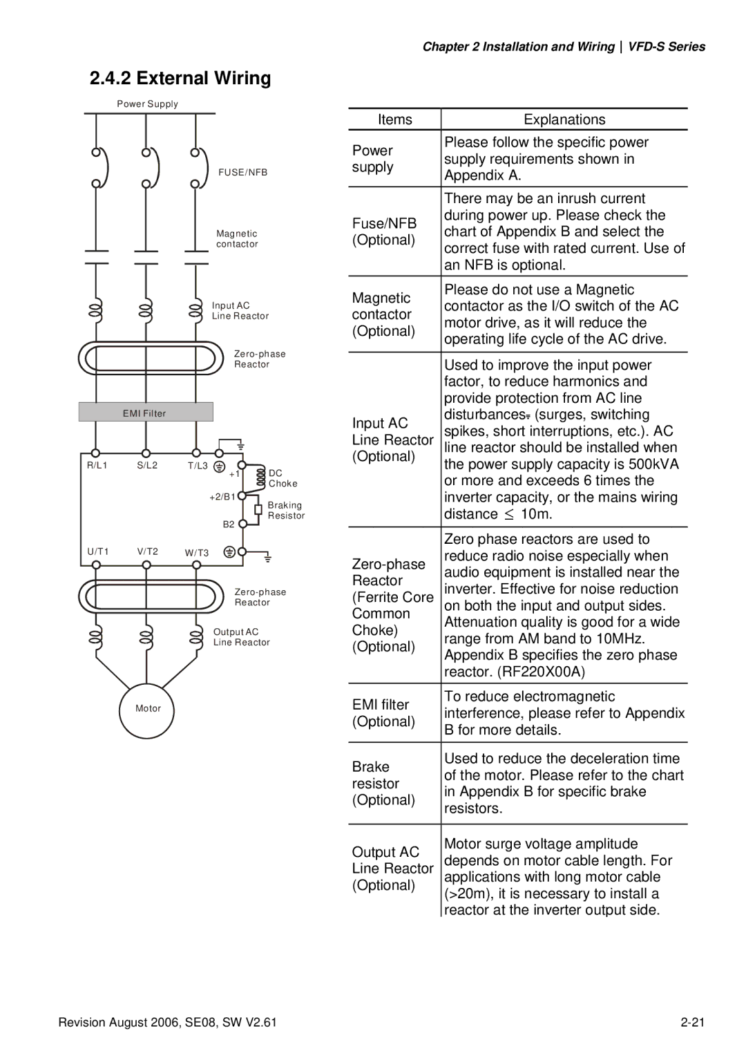
2.4.2 External Wiring
Power Supply
|
|
|
|
|
|
|
|
|
| FUSE/NFB |
|
| |||||||
|
|
|
|
|
|
|
|
|
| Magnetic |
|
| |||||||
|
|
|
|
|
|
|
|
|
|
|
| ||||||||
|
|
|
|
|
|
|
|
|
| contactor |
|
| |||||||
|
|
|
|
|
|
|
|
|
| Input AC |
|
| |||||||
|
|
|
|
|
|
|
|
|
|
|
| ||||||||
|
|
|
|
|
|
|
|
|
|
|
| ||||||||
|
|
|
|
|
|
|
|
|
| Line Reactor | |||||||||
|
|
|
|
|
|
|
|
|
|
|
|
|
| ||||||
|
|
|
|
|
|
|
|
|
|
|
|
|
| ||||||
|
|
|
|
|
|
|
|
|
|
|
|
|
| ||||||
|
|
|
|
|
|
|
|
|
|
|
|
|
| Reactor | |||||
|
|
|
|
|
|
|
|
|
|
|
|
|
|
|
|
|
|
|
|
|
|
|
| EMI Filter |
|
|
|
|
|
|
|
|
|
|
|
| |||
|
|
|
|
|
|
|
|
|
|
|
|
|
|
|
|
|
|
|
|
| R/L1 |
| S/L2 | T/L3 |
|
|
|
|
| DC | |||||||||
|
|
|
|
|
|
|
| +1 |
|
| |||||||||
|
|
|
|
|
|
|
|
|
|
|
|
|
|
|
|
|
| Choke | |
|
|
|
|
|
|
|
|
|
| +2/B1 | Braking | ||||||||
|
|
|
|
|
|
|
|
|
|
|
|
|
|
|
|
|
| ||
|
|
|
|
|
|
|
|
|
|
|
| B2 | Resistor | ||||||
|
|
|
|
|
|
|
|
|
|
|
|
|
| ||||||
| U/T1 |
| V/T2 | W/T3 |
|
|
|
|
|
|
| ||||||||
|
|
| |||||||||||||||||
|
|
|
|
|
|
|
|
|
|
|
|
|
| ||||||
|
|
|
|
|
|
|
|
|
|
|
|
|
| ||||||
|
|
|
|
|
|
|
|
|
|
|
|
|
| Reactor | |||||
|
|
|
|
|
|
|
|
|
| Output AC |
|
| |||||||
|
|
|
|
|
|
|
|
|
|
|
| ||||||||
|
|
|
|
|
|
|
|
|
|
|
| ||||||||
|
|
|
|
|
|
|
|
|
| Line Reactor | |||||||||
|
|
|
|
|
|
|
|
|
|
|
|
|
|
|
|
|
|
|
|
|
|
|
|
|
|
|
|
|
|
|
|
|
|
|
|
|
|
|
|
|
|
|
|
| Motor |
|
|
|
|
|
|
|
|
|
|
|
| ||
Chapter 2 Installation and
Items | Explanations | |
Power | Please follow the specific power | |
supply requirements shown in | ||
supply | ||
Appendix A. | ||
| ||
| There may be an inrush current | |
Fuse/NFB | during power up. Please check the | |
chart of Appendix B and select the | ||
(Optional) | ||
correct fuse with rated current. Use of | ||
| ||
| an NFB is optional. | |
Magnetic | Please do not use a Magnetic | |
contactor as the I/O switch of the AC | ||
contactor | ||
motor drive, as it will reduce the | ||
(Optional) | ||
operating life cycle of the AC drive. | ||
| ||
|
| |
| Used to improve the input power | |
| factor, to reduce harmonics and | |
| provide protection from AC line | |
Input AC | disturbances. (surges, switching | |
spikes, short interruptions, etc.). AC | ||
Line Reactor | ||
line reactor should be installed when | ||
(Optional) | the power supply capacity is 500kVA | |
| ||
| or more and exceeds 6 times the | |
| inverter capacity, or the mains wiring | |
| distance ≤ 10m. | |
|
| |
| Zero phase reactors are used to | |
reduce radio noise especially when | ||
audio equipment is installed near the | ||
Reactor | ||
inverter. Effective for noise reduction | ||
(Ferrite Core | ||
Common | on both the input and output sides. | |
Attenuation quality is good for a wide | ||
Choke) | ||
range from AM band to 10MHz. | ||
(Optional) | ||
Appendix B specifies the zero phase | ||
| ||
| reactor. (RF220X00A) | |
EMI filter | To reduce electromagnetic | |
interference, please refer to Appendix | ||
(Optional) | ||
B for more details. | ||
| ||
Brake | Used to reduce the deceleration time | |
of the motor. Please refer to the chart | ||
resistor | ||
in Appendix B for specific brake | ||
(Optional) | ||
resistors. | ||
| ||
|
| |
Output AC | Motor surge voltage amplitude | |
depends on motor cable length. For | ||
Line Reactor | ||
applications with long motor cable | ||
(Optional) | (>20m), it is necessary to install a | |
| reactor at the inverter output side. |
Revision August 2006, SE08, SW V2.61 |
