System expansions | Boards in |
| |
|
|
|
|
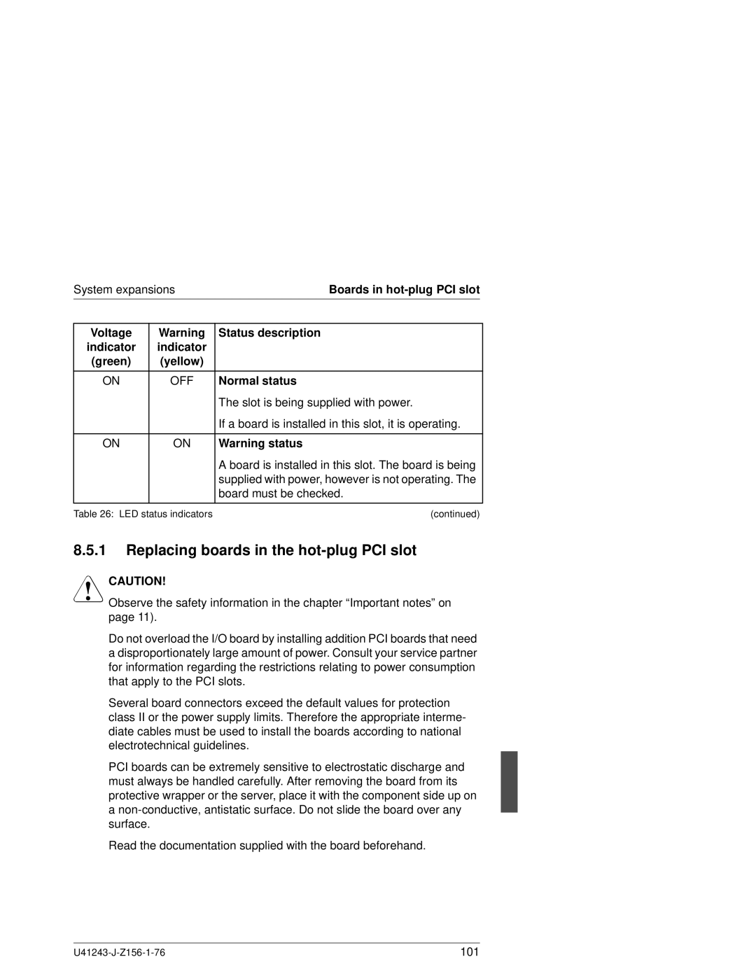
Voltage | Warning | Status description |
|
indicator | indicator |
|
|
(green) | (yellow) |
|
|
|
|
|
|
ON | OFF | Normal status |
|
|
| The slot is being supplied with power. |
|
|
| If a board is installed in this slot, it is operating. |
|
|
|
|
|
ON | ON | Warning status |
|
|
| A board is installed in this slot. The board is being |
|
|
| supplied with power, however is not operating. The |
|
|
| board must be checked. |
|
|
|
|
|
Table 26: LED status indicators | (continued) |
| |
8.5.1Replacing boards in the hot-plug PCI slot
VCAUTION!
Observe the safety information in the chapter “Important notes” on page 11).
Do not overload the I/O board by installing addition PCI boards that need a disproportionately large amount of power. Consult your service partner for information regarding the restrictions relating to power consumption that apply to the PCI slots.
Several board connectors exceed the default values for protection class II or the power supply limits. Therefore the appropriate interme- diate cables must be used to install the boards according to national electrotechnical guidelines.
PCI boards can be extremely sensitive to electrostatic discharge and must always be handled carefully. After removing the board from its protective wrapper or the server, place it with the component side up on a
Read the documentation supplied with the board beforehand.
101 |
