Controls and indicators | Preparation for use and operation |
4.1.7Rear view
|
|
|
|
|
| 1 4 | 1 3 | 1 2 | 1 1 | |
1 5 |
|
|
|
|
|
|
|
|
|
|
1 0 9 | 8 | 7 | 6 | 5 | 4 | 3 | 2 | 1 |
|
|
1 6 |
|
|
| 1 6 |
|
| 1 6 |
|
| |
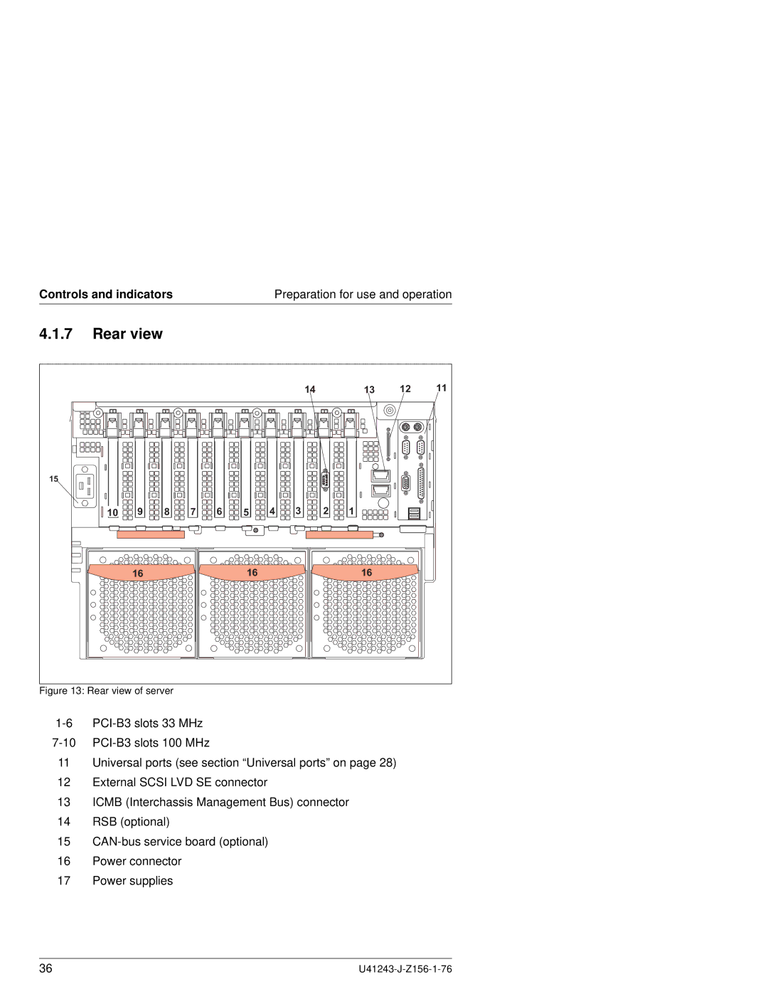
Figure 13: Rear view of server
11Universal ports (see section “Universal ports” on page 28)
12External SCSI LVD SE connector
13ICMB (Interchassis Management Bus) connector
14RSB (optional)
15
16Power connector
17Power supplies
36 |
