Manuals
/
Fujitsu
/
Computer Equipment
/
Server
Fujitsu
N800
manual
Processor expansion, Processor unit and FSB terminator
Models:
N800
1
114
142
142
Download
142 pages
2.29 Kb
111
112
113
114
115
116
117
118
Troubleshooting
Install
Error codes
Password
Drive error
Controls and indicators
Connecting cables
Dimension
Scsi configurations
Externally accessible drives
Page 114
Image 114
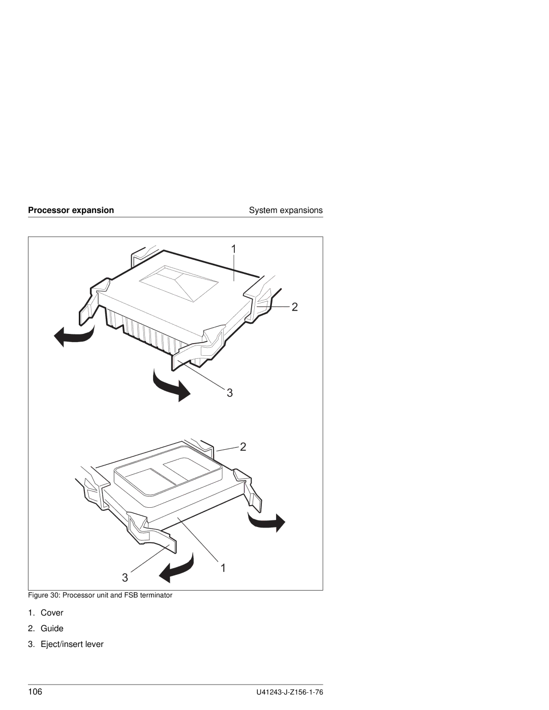
Processor expansion
System expansions
1
2
3
2
1
3
Figure 30: Processor unit and FSB terminator
1.
Cover
2.
Guide
3.
Eject/insert lever
106
U41243-J-Z156-1-76
Page 113
Page 115
Page 114
Image 114
Page 113
Page 115
Contents
Primergy N800 Server System
Comments… Suggestions… Corrections…
Copyright and Trademarks
Page
Page
Contents
Contents
Configuration software and utilities
105
Page
Introduction
Externally accessible drives
Features
Features
Processors and Memory
Cooling
Power supply
Introduction
Hot-plug PCI
Server management
ServerStart
Service and Support
Other features
Target group
Summary of contents
System expansions
Scsi configurations
Notational conventions
Bold type
User-friendly documentation verified quality
User-friendly documentation verified quality
Electrical data
Technical data
Dimensions and weight
Environmental conditions according to DIN EN
Technical data
Standards
Noise level ISO Operation Idle
Important notes
Important notes
Electrostatic-sensitive component label
Electrostatic-sensitive component sticker
FCC notices Federal Communications Commission
CE certificate
RFI suppression
CE certificate
Important notes
Environmental protection
Environmental protection
Environmentally friendly product design and development
Take-back, recycling and disposal
Further information on environmental protection
Page
Installing the server
Unpacking the server
Mounting the installation kit and the server
Mounting the server in the rack
Mounting the server in the rack
Mounting the server in the rack
Mounting the system brackets
Press in the safety springs 1 on both telescopic rails
Mounting the articulated cable guide
Connecting and disconnecting cables
Connecting cables
Disconnecting cables
Routing cables
Routing cables
Inch Rack
DataCenter Rack
Routing the cables in the DataCenter Rack
Connecting devices to the server
Connecting devices to the server
Universal ports
Can bus connection
ServerView and the can bus
PCI can bus controller
Connecting the server to line voltage
RemoteView RTDS, Seman and the can bus
Page
Controls and indicators
Preparation for use and operation
Control panel
Controls and indicators
Drive error
Controls and indicators for the floppy disk drive
Indicators for the internal Scsi drives
Controls and indicators for the CD-ROM drive
Indicators for the power supplies
Rear view
Rear view of server
Switching the server on and off
Installing the operating system
Installing the operating system
Configuring the server and components
Switch Function Description Pos
Changing the switch settings
A r Id e
Meaning
Lupk
Cleaning the server
Password Clear
Page
Power-ON Self-Test Post
Configuration software and utilities
Short cuts using a key combinations
Key combinations
Power-ON Self-Test Post
Bios Setup
Recording Setup settings
You cannot call Bios Setup
Starting Bios Setup
Bios Setup
Setup menus
Pos Main menu Submenu
Display Meaning
Key Meaning
Menu item Option Description
Disabled
Main Menu
44/1,25 MB, 3 ½
English US
Auto
Option Description
Processor Information submenu
Menu item Description
Keyboard Features submenu Menu item Option Description
30/sec
Sec
Enabled
Advanced Menu
Minimum
PCI Configuration submenu Menu item Option Description
PCI
PCI Mode submenu Menu item Option Description
0080h
3F8
2F8
Bidirectional
378h
DMA
Causes the secondary cache to be
Security Menu
Clear
Secure Mode Boot
Server Menu
Direct Connect
Enable
System Management submenu Menu item Option Description
Server Management Information submenu
Console Redirection submenu Menu item Option Description
9600
Boot Menu
Bios Setup Menu item Option Description
Exit Menu
System Setup Utility SSU
Utilities
Utilities
Creating bootable floppy disks
Bios update
Recording the current Bios settings
Preparations
Bios and firmware update
Example
Recovering Bios
Changing the Bios language
QLogic Scsi utility
Installing graphic drivers
Installing PCI hot-plug software
Running the Scsi utility
Password protection
Secure boot mode
Property and data protection
Locking the power and reset buttons
Boot sequence control
Boot without keyboard
Floppy disk write protection
Power cable incorrectly connected
Troubleshooting and tips
Power-on indicator remains dark
Power supply overloaded
Server switches itself off
Screen remains dark
No mouse pointer displayed on the screen
Flickering stripes on the monitor screen
No screen display or display drifts
Monitor does not support the set horizontal frequency
Floppy disk cannot be read/written
System will not boot
Scsi configuration incorrect Ultra Wide Scsi controller
Time and date are not correct
Drives are reported as dead
Error messages on the screen
Configuration of the disk array controller is incorrect
Added drive reported defective
Error messages on the LCD display
Error messages on the LCD display
Code Error message
Error messages on the LCD display
Error messages on the LCD display
Code Error message
Error messages on the LCD display
System expansions
Opening/closing the server
Removing the front bezel
Mounting the front bezel
Opening/closing the server
Removing/mounting the PCI bus hot-plug cover
Removing the PCI bus hot-plug cover
Removing/mounting the top cover
Removing the top cover
Scsi hard disk drives
S y Fault
Scsi hard disk drives
Replacing Scsi hard disk drives
LED
Removing a hard disk drive
System expansions
Power supply units
Power supply units
Replacing a power supply unit
LED
Fans
Fans System expansions
Replacing a fan
Fans
Fans System expansions
Removing a fan
Boards in hot-plug PCI slot
PCI locking mechanism
Voltage Status description
LED indicators
Boards in hot-plug PCI slot
Emergency-off status
Replacing boards in the hot-plug PCI slot
Normal status
Release the PCI locking mechanism and remove the board
103
Adding a PCI board
Removing the PCI slot cover
Processor expansion
Processor expansion
Processor unit and FSB terminator
Removing/installing processor units
Removing the processor fastener U41243-J-Z156-1-76
Memory expansion
Memory expansion
Single port mode one memory module The single memory module
Need to be installed in pairs
Installing DIMMs
Step Occupied sockets
111
Removing a memory module
Removing the memory module cover
113
Installing a memory module
RemoteView storage medium
RemoteView storage medium
Configuring the RemoteView storage medium
Remote Service Board
Remote Service Board
Scsi configurations
Configuration SCSI-IDs
Addresses for Scsi devices
Internal Scsi configurations
Internal Scsi configurations
Configuration with dual onboard Scsi controller default
Abbreviations
Abbreviations
HSC
PCI
SEL
Page
Related publications
Safety, Warranty and Ergonomics Zoll-Rack/19 Inch Rack
Can Multi Mode Faser
Primergy S40-DF Storage Subsystem Operating manual
Page
Bios
Index
Indicator
Index
Mains
129
Height units Mounting in the rack ON/OFF switch Ports
Comments Suggestions Corrections
Page
Comments Suggestions Corrections
Top
Page
Image
Contents