Preparation for use and operation Configuring the server and components
Recovery Boot:
This switch controls whether the system attempts to boot using the BIOS code stored in flash memory, or, if the BIOS code is corrupt, whether a recovery boot is performed by loading the BIOS code from a floppy disk into flash memory.
If you want to start a recovery boot, proceed as follows:
ÊFollow the procedure described in the section “Changing the switch settings”.
ÊSet DIP switch 2 (see table 2 on page 38) to ON.
ÊInsert the flash memory update floppy disk in drive A.
ÊTurn on the system.
After the system boots, a single beep is emitted and the recovery process is started. This takes about three minutes. Once the recovery process has been completed, two beeps are emitted.
During recovery, there is no screen display on the monitor and the keyboard is disabled.
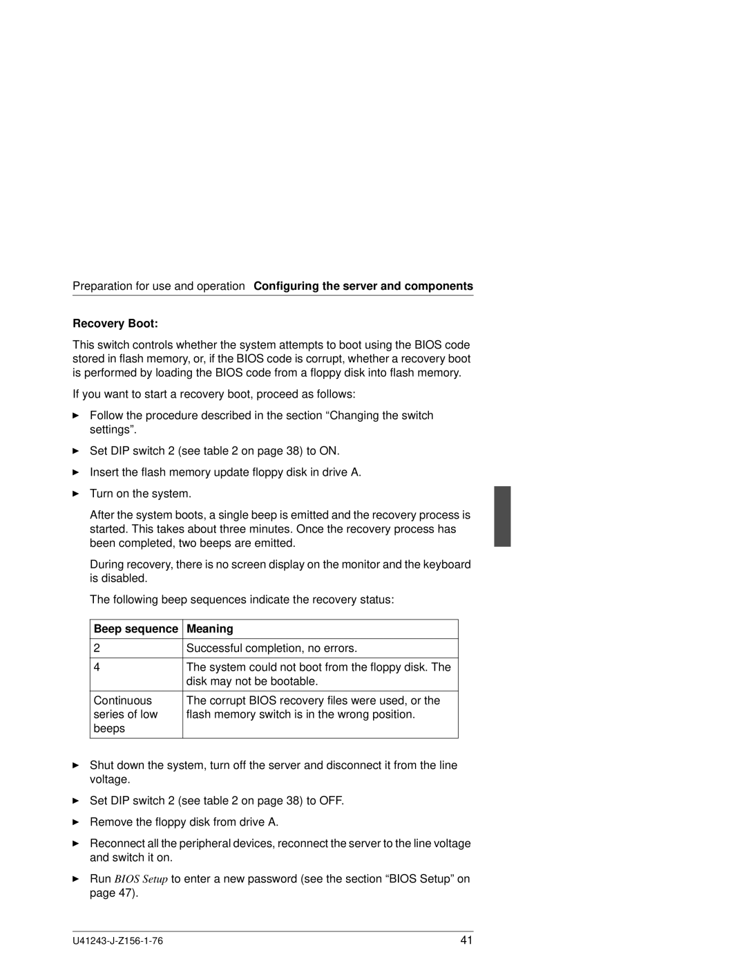
The following beep sequences indicate the recovery status:
Beep sequence | Meaning |
|
|
2 | Successful completion, no errors. |
|
|
4 | The system could not boot from the floppy disk. The |
| disk may not be bootable. |
|
|
Continuous | The corrupt BIOS recovery files were used, or the |
series of low | flash memory switch is in the wrong position. |
beeps |
|
|
|
ÊShut down the system, turn off the server and disconnect it from the line voltage.
ÊSet DIP switch 2 (see table 2 on page 38) to OFF.
ÊRemove the floppy disk from drive A.
ÊReconnect all the peripheral devices, reconnect the server to the line voltage and switch it on.
ÊRun BIOS Setup to enter a new password (see the section “BIOS Setup” on page 47).
41 |
