Ethernet Interface User’s Manual
Page
Ethernet Interface User’s Manual
First Edition May
Internet
Energy Star
Page
Page
Page
Trademarks
Product Recycling and Disposal
Communication Statements
Federal Communications Commission FCC Statement
European Union EU Conformity Statement
Industry Canada Compliance Statement
533
German Conformity Statement
Handbuchtexte FCC class a entspricht Emvg Klasse a
China
Declaration
Taiwannese
Lithium Battery Warning
Korea
Object Code License
Software License Agreement
Source Code
No Warranty
Conflicting Terms
Limitation of Liability
S. Government Users
Miscellaneous
Red Hat Statement with regards to eCos Software
IBM Product Registration Web site
Product Registration Information
Register your new IBM printer today
Page
Page
Table of Contents
Embedded Ethernet Interface Web
Windows Configuration
AIX/Unix Configuration
Novell Configuration
ISeries Configuration, Ascii Printer
ISeries Configuration, Ipds Printer
Addtcpifc
11 z/OS Configuration, TN3270E
MIB
Snmp
Glossary 375
What Is The Ethernet Interface?
Overview
Printer Models And Applicable Ethernet Interface Cards
What Special Features Are Available?
Printer Ethernet Interface Card Type
What Special Features Are Available?
Logical Printer Architecture
Logical Printer Architecture
Phase
Destinations/Queues
Models
Models
Interfaces
Run and Auto Reset Modes
10/100Base-T
Stat
Network Indicator
NET LED Indicator
Indication Description
Ethernet Integrated NIC Card LED
Wireless Network Indicator
Integrated NIC LED Indicator
Stat LED
10/100Base-T
NET LED
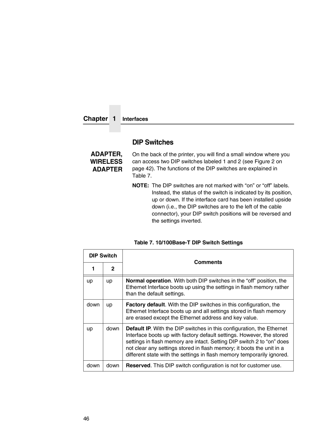
100Base-T DIP Switch Settings
DIP Switches
DIP Switch Comments
Speed Setting for 10/100Base-T
Conventions Used In This Manual
Ping ftp.CompanyWebsite.com
Page
Page
Installation
Wireless Connecting To The Network
Configuration Tools
Configuration Tools
Configuration Using The Control Panel
Configuration Using The Control Panel
Configuration Tools
Page
Configuration Tools
Ethernet Interface Verification
Ethernet Interface Verification
Network Interfaces TCP/IP Routing Table
IP Address Configuration
Wireless Ethernet Interface Configuration Using
Control Panel
Operation Mode
Wireless Parameter Configuration
Signal Strength
Gateway Address
Channel
Configuration Tools Ssid Name
Minimum Transfer Rate
Antenna Diversity
International Mode
Power Management
Transmit Power
Authentication Method
WEP Key x Format
Encryption Key Configuration
Authentication Method
WEP Key x Width
Kerberos Parameters
Kerberos Enable
Reset Kerb. Pwd
Kerb. Pwd
Clock Skew SEC
Configuration Tools Clock Skew Units
Tckt Life Units
Renew Life Units
Renew Life SEC
Wireless Cisco Leap
Configuring the Print Server for Kerberos Authentication
Wireless Kerberos Enabled Wireless NIC Configuration
Kerberos Enabled Wireless NIC Configuration
Configuration Tools
Html Forms
Html Forms
Ethernet Interface Html Structure
Printer Status Screen
Printer Status Screen
Telnet
Configuration Alternatives
Remote Shell
Embedded Ethernet Interface Web
Configuration
Configuration
Configuration
Network Configuration
Network Configuration
TCP/IP Network
Routing
Interface
TCP/IP Network
Network Name
802.11b
Mode
Speed
Power Management Mode
Transmit Power
Channel
Password
Default Key
User
Windows Network NetBIOS TCP/IP
Windows Network NetBIOS TCP/IP
Workgroup Name
Novell Network
FrameType
Pserver
Service Type
File Server
Rprinter
Print Path Configuration
Print Path Configuration
Destination Settings
Name
Selected Model
Services
Destination Settings
Parameters
Current Model Settings
Selected Log Path
Current Log Path Settings
Printer Configuration
Log Path Type
Print Model Configuration
Print Model Configuration
Banner
Trailer String
Log Path Configuration
Log Path Configuration
Logpath Type
Logpath Port
TN5250/3270 Configuration
TN5250/3270 Configuration
TN5250/3270 Configuration, TN3270 Mode
Host IP
Device Description
Port
Resource Name
Message Queue Name
Wscst Library
Device Type
Wscst Name
Auto Connect
Snmp Manager Alert Posting Settings
Snmp Configuration
Snmp Configuration
Syslog Alert Posting Settings
Email Alert Posting Settings
Short E-mail Message Length
Email Address
Short E-mail Format
Send Test Message
Snmp Alert Groups Configuration
Alert Groups
Snmp Configuration Alert Groups and Printer Events
Snmp Configuration Alert Groups and Printer Events
Snmp Configuration Alert Groups and Printer Events
Rfid
System Information
Administration Configuration
System Information
Location
Administration Configuration
Description
Contact
Smtp Server
Syslog
DNS Server
Passwords
System Configuration
System Configuration
Status I/O Port
Status
Status I/O Port
Status Network
IBM Printing Systems
IBM Printing Systems
Windows Configuration
Windows Environment Description
Windows Ethernet Interface Configuration
Windows Ethernet Interface Configuration
Configuration Using ARP
Mandatory
Configuration Using ARP
Communicating Across Routers
Changing Workgroup Names
Changing Workgroup Names
Changing Destination Names
Ethernet Interface Default Destinations Mapped I/O Port
PRN
Changing Destination Names
Windows Host Configuration
Windows Host Configuration
Windows XP/2000 Host Setup
Settings Printers
Windows XP/2000 Host Setup
Click Next 120
Select Custom and click Settings
Windows Host Configuration
Click Next Click Finish 123
Select Yes then click Next 124
Windows XP/2000 Host Setup
Windows NT 4.0 Host Setup
Select Start Settings Printers
Windows NT 4.0 Host Setup
Click Add Port
Windows Host Configuration
Enter a name for the printer in the Printer Name field 129
Windows Host Configuration
Windows NT 3.51 Host Setup
Windows NT 3.51 Host Setup
Windows Me or 9x Host Setup
Add LPR Compatible Printer Dialog Box
Windows Me or 9x Host Setup
Technical Support
Windows Troubleshooting Tips
Windows Troubleshooting Tips
Ethernet Interface Cannot Be Found On Network
Errors Occur When Defining An LPR Printer
Html Configuration Forms Will Not Display
Html Configuration Forms Will Not Display
Printer Errors When Printing Or No Output
Cannot Browse The Ethernet Interface On The Network
TCP/IP Access Problem
TCP/IP Access Problem
Wireless Ethernet
Windows NT 4.0 Or 2000 Host Setup Problems
Web Browser/HTTP Problem
Web Browser/HTTP Problem
Installing Microsoft TCP/IP Printing
Windows NT 4.0 Or 2000 Host Setup Problems
142
AIX/Unix Configuration
Unix Environment Description
Using ARP
Unix Ethernet Interface Configuration
Unix Ethernet Interface Configuration
Using ARP
Using Rarp
Using Bootp
Using Bootp
Bootp
Communicating Across Routers
Manual System V Host Setup
Unix Host Configuration
Manual System V Host Setup
Ethernet Installation on HP-UX
Ethernet Installation on HP-UX
Explanation of command line
Troubleshooting
Solaris 2.6 7 Ethernet Setup
Solaris 2.6 7 Ethernet Setup
SCO Setup
SCO Setup
SCO Setup
Salesdept
SCO Setup
SCO Setup
#lp -dprintname filename
Manual LPR/LPD Host Setup
Manual LPR/LPD Host Setup
Start the printer daemon for this new printer. Example
Standard Processing
Ethernet Configuration for AIX
Ethernet Configuration for AIX
Select Printer/Plotter Select Print Spooling
Local Filtering
Troubleshooting
Enter smitty mkvirprt
Diagnostics
AIX Remote Queue Time-Out Setting
AIX Remote Queue Time-Out Setting
Printing With FTP
Change to the dest directory. Syntax
Direct Socket Printing
Printing From AIX
Direct Socket Printing
Setting Up AIX
Printing From AIX
Unix Troubleshooting Tips
Ethernet Interface Cannot Be Found On The Network
Unix Troubleshooting Tips
Nothing Prints
Stair-Stepped Output
Stair-Stepped Output
No Form Feed Or Extra Page Comes Out
Store tcpip from default config http on Reset
ETHERNET, Wireless
Front Panel Message Dynamically Set Params Read Only
Novell Configuration
Novell Environment Description
Mandatory
Novell Ethernet Interface Configuration
Novell Ethernet Interface Configuration
Optional
Using Html Forms
Using Html Forms
NetWare Version 3. x Pserver Setup
Novell Host Configuration
Novell Host Configuration
NetWare Version 3.x Pserver Setup
Enter
Novell Host Configuration
NetWare Version 3.x Rprinter Setup
NetWare Version 3.x Rprinter Setup
Novell Host Configuration
NetWare Version 3.x Rprinter Setup
NetWare Version 4.x and 5.x Pserver Setup
NetWare Version 4.x and 5.x Pserver Setup
Npsh unitname
NetWare Version 4.x and 5.x Rprinter Setup
NetWare Version 4.x and 5.x Rprinter Setup
Store rprinter add FinQ 2 d4prn
Novell Troubleshooting Tips
Novell Troubleshooting Tips
NetWare 3.x No Pserver Connection
NetWare 4.x and 5.x- No Pserver Connection
NetWare 4.x and 5.x- No Pserver Connection
190
Novell Configuration For 10/100Base-T Interfaces
Ethernet Interface Configuration. This section includes
Preferred File Server NDS and Bindery Setups
Novell Ethernet Interface Configuration 10/100Base-T
Novell Ethernet Interface Configuration 10/100Base-T
Html Method
Preferred File Server NDS and Bindery Setups
Adding Preferred File Server
Manual Telnet Method
Removing Preferred File Server
Netware 4.x
Setting Password Security NDS and Bindery Setups
Setting Password Security NDS and Bindery Setups
Netware
Print Server Setup Html Method
Print Server Setup Manual Telnet Method
Adjusting Polling Time NDS and Bindery Setups
Adjusting Polling Time NDS and Bindery Setups
Changing The Ethernet Interface Name NDS and Bindery Setups
Html Method
Changing The Ethernet Interface Name NDS and Bindery Setups
Manual Telnet Method
Http//EthernetInterfaceIPaddress/ networkConf.html
Changing The Ethernet Interface Mode NDS and Bindery Setups
Changing The Ethernet Interface Mode NDS and Bindery Setups
Setting The Ethernet Interface NDS Context NDS Setups
Setting The Ethernet Interface Preferred NDS Tree NDS Setups
Novell Host Configuration 10/100Base-T
Novell Host Configuration 10/100Base-T
NDS Pserver Setup Netware 4.x/5.x
NDS Pserver Setup Netware 4.x/5.x
Novell Host Configuration 10/100Base-T
NDS Pserver Setup Netware 4.x/5.x
Bindery Pserver Setup Netware 3.x, Netware 4.x, and Netware
Load pserver .salesps.sales.microplex
Telnet to the print server telnet ipaddress 210
Ipaddressroot
Ndps Configuration Netware 4.11 and Above
Overview
Setup using LPR Mode
Setup using Forward Jobs to a Queue Mode
Ndps Configuration Netware 4.11 and Above
Setup Using Rprinter Mode
Pserver Setup
Troubleshooting 10/100Base-T
Pserver Setup
Pserver
Troubleshooting 10/100Base-T
Pserver Setup
RPRINTER/NPRINTER Setup
RPRINTER/NPRINTER Setup
Printing Related
Job Goes To The Queue But Nothing Prints
Job Prints Incorrectly
Printing Related
222
ISeries Configuration Ascii Printer
Developing Line Descriptions With Crtlineth
Example Ethernet Interface Line Description
Configuring With Addtcpifc
Configuring iSeries For Ascii Using TCP/IP
Ssap
None
Configuring iSeries For Ascii Using TCP/IP
Internet Address
Configuring a Router Definition With
Configuring a Local Domain And Hostname
Setting Up Printing For Ascii Files
Configuring The iSeries For Printing
Configuring a TCP/IP Host Table Entry
Remote Printer Queue name
To Use LPR Manually
NO, *YES
Curlib
YES NO, *YES
To Create An Automatic Remote Output Queue
User
YES YES, *NO
Libl
SNA SNA, *IP, *USRDFN
None NONE, *IMGA01
Output Queue Outq
Remote System Rmtsys
Connection Type Cnntype
Writer to Autostart Autosrtwtr
Destination Options Destopt
= *WSCSTCONT132
= *NONE
= Qsys
Verify Printing On iSeries
VDIAGNOSTICS Printer Tests E-net Test Enter
Verify Printing On iSeries Internet address Intnetadr
ISeries Ascii Troubleshooting
ISeries Ascii Troubleshooting
TCP/IP Access Problem
Arp -sipaddress MACaddress ping ipaddress
Web Browser/HTTP Problem
Configuring On iSeries As An Ipds Printer
Printing AFP, IPDS, And SCS Files
Control Panel Settings Menu
Configuration Checklist
Configuring On iSeries As An Ipds Printer
Requirements
Configuring An iSeries TCP/IP Interface With
Configuring An iSeries TCP/IP Interface With Addtcpifc
Type of service
Configuring An Interface For Ethernet
Normal
Configuring a TCP/IP Host Table Entry
Configuring PSF For Ipds On V3R7 Or V4R1
Configuring AFP With Crtpsfcfg On V3R7 Or V4R1 Optional
Remote location Name or address
Configuring PSF For Ipds On V3R7 Or V4R1
TCP/IP activation timer 170
TCP/IP port
Release timer Rlstmr
PSF configuration Psfcfg
Activate release timer Actrlstmr
Ipds pass through Ipdspasthr
Configuring PSF With Crtdevprt On V3R7 Or V4R1
Formfeed Cont
Port
Font
Acttmr
Form Feed Formfeed Specify *CONT Activation Timer Acttmr
Remote Location Rmtlocname
Configuring AFP with Crtpsfcfg on V4R3 and above Optional
Configuring PSF for Ipds On V4R2 And Above
Crtdevprt
Nomax
Blank
YES
None NONE, *CHKFIRST, *CHKALL
Libcrtaut
Remote Location name or address Rmtlocname
Configuring PSF with Crtdevprt On V4R2 and above
Configuring PSF for Ipds On V4R2 And Above
256
Device Type Type
Device Description Devd
Device Class Devcls
Device Model Model
Configuring On iSeries As An Ipds Printer Font Font
Form Feed Formfeed
Verifying The Ipds Configuration On iSeries
Verifying The Ipds Configuration On iSeries
Sharing The iSeries Printer On The Network
Sharing The iSeries Printer On The Network
Printer Sharing ISeries
Printer Sharing Parameters
Printer Sharing Parameters
Parameter
Crtdevprt Acttmr Nomax
ISeries Troubleshooting
Cannot Ping The Printer
Chgdevprt
PSF Terminates When Initialized
PSF Terminates When Initialized
Spooled Print File Remains In PND Status
Spooled Files Disappear Without Printing
ISeries Troubleshooting
Data Is Being Clipped
10 z/OS Configuration Ipds Printer
Configuration Checklist
Configuration Procedure
Configuring PSF for z/OS to Print Ipds Files
Configuration Procedure
Modify the TCP/IP Profile in z/OS
Configuring PSF for z/OS to Print Ipds Files
Define the Communications Control Unit to z/OS
Mvscp
Modifying TCP/IP Profile
Tinydatabufferpoolsize
Databufferpoolsize
Smalldatabufferpoolsize
Keepaliveoptions
Verify the Printer Connection
Gateway
JES2 Printer Definitions
Define the Printer to JES
JES3 Printer Definitions
Define the Printer to PSF
274
275
Sample Psfproc procedure
Ipaddr
Stopping a TCP/IP-attached Printer
Verifying a TCP/IP-Attached Printer on z/OS
Starting a TCP/IP-attached Printer
Verifying a TCP/IP-Attached Printer on z/OS
JES Spool Printer Sharing
Resolving Ipds Printing Problems
Sharing IBM 6500-v Printers on z/OS
Sharing IBM 6500-v Printers on z/OS
Mgmtmode
Timeout
JES Spool Printer Sharing
Failure
Handling z/OS Connectivity Problems
Handling z/OS Connectivity Problems
Port Switching Printer Sharing
Ping is Not Successful
Ping is Successful
Ping is Successful
282
Coax Printer Support Fmid
OS Configuration For a TN3270E Printer
HPRT100
PRT9 and Fssdef for
Program Materials
Program Materials
Courwtr Proc
Vtam Definitions For SCS and DSE TN3270E
Vtam Definitions For SCS and DSE TN3270E
JES2 TN3270E Vtam Major Node
Printer with SNA Character SET LU1
Tcpip Configuration With TN3270E
Tcpip Configuration With TN3270E
TN3270E
FSA
Printer Inventory Manager As Defined With TN3270E
FSS
Program Materials
VTAMSCS1
VTAMDSE1
VTAMSCS2 Ippw
Program Materials
FCB Segment
Linect
Dest Prmode
Threshld
Program Materials
Printer Inventory Manager As Defined With TN3270E
Program Materials
Configuration Forms
Configuration Screens
Configuration Screens
Configuration Html Forms
IBM
RMT3 *PRINTER PPE LU3PRT
Active Prof Curr Conns 3 Records Displayed
300
ISeries Configuration TN5250
Setting Up TN5250 Print Queues on iSeries
Setting Up a TN5250 Connection/Device Via a Telnet Session
Setting Up a TN5250 Connection/Device Via a Telnet Session
Store Commands
Using Telnet Commands for TN5250
Command List
User Supplied Values
Using Telnet Commands for TN5250
List Commands
TN5250/3270 Auto Connect Command
Getting Started
Devd
TN5250 Job Formatting
TN5250 Job Formatting
Online
Mfrtypmdl Same
Prtermsg Info
Transform
PPRSRC1 Mfrtypmdl
Font Identifier Font Help
Font Identifier Font Help
Wscst None
308
Device Type Type
Configuration Instructions
Device Class Devcls
Device Model Model
Port number Port
Printer Error Message Prterrmsg
Activation Timer Acttmr
Font Font =
Host Print Transform Transform
Inactivity Timer Inacttmr
Configuration Instructions
Manufacturer Type and Model Mfrtypmdl
System Driver Program Sysdrvpgm
User-Defined Options Usrdfnopt
Workstation Customizing Object Wscst
LCL, *RMT, *VRT, *SNPT, *LAN
Configuration Example
P6500
LEXLINK, *IP, *USRDFN
‘9.5.208.46
INQ INQ, *INFO
Ctld
DTAARA, *DTAQ, *FILE
Unknown UNKNOWN, *SIMPLEX, *DUPLEX
Varying on the Printer
Varying on the Printer
Unknown
Problem Areas for Consideration
Additional Information
Additional Information
318
Implementing Printer Management
Agent/Manager Model
Components Of The Printer MIB
Standards Of Network Printer MIBs
Implementing Printer Management
Getting The Latest MIB Information
Information Provided By The MIB
General Information About MIBs
MIB
Monitoring With AIX NetView/6000
Monitoring Tools
Monitoring Tools
Setting The Snmp Community Name
Setting The Snmp Community Name
Printer Management Utility Software PMU
324
IBM Network Printer Manager
IBM Network Printer Manager
Npsh Access Methods
Command Shell Overview
Main npsh Command Prefixes
? Command
Complete Command List
Getting Command Help
Command Prefixes
Store Commands
Store Commands
Define a auth-user-name to be used in the Leap operation
Set antenna type
Set the default key for Wlan encryption
Interoperability recommends that your system clock be
Configures the KDC realm portion
Command to change the print server name
Complete Command List
ADAPTER, Wireless
ADAPTER, Wireless Adapter
Store the subnet mask for the Ethernet Interface
Example store tcpip tcp opts zeroIPArp
Set all TCP/IP network settings back to factory defaults
Complete Command List
Store tn from defaultcurrent Example store tn from default
Set Commands
Set Commands
Cksum
Job
User
Printer
Descramble
Onlcr
Xtab
Set all model settings back to factory defaults 348
Flush the data in the parallel port input and output buffers
Set prn from stored
Set snmp trap index -active
Example set snmp alerts 1 warning -cutter
Set Commands
Set sysinfo syslog IPaddress Example set sysinfo syslog
Set all user settings back to factory defaults
List Commands
List Commands
Wlan
For Wireless Ethernet with Symbol RF cards only
List the MOS version
Miscellaneous Commands
Miscellaneous Commands
Ping -shostIPaddress datasize packetnumber
Tts
Fox
Loopb
364
Users And Passwords
Ethernet Interface Security
Ethernet Interface Security
Reset The Ethernet Password
Reset The Ethernet Password
Procedure a
Save reset
Procedure B
Procedure C
TCP Access Lists
TCP Access Lists
370
Printer And Print Job Monitoring
Printer Monitoring And Logging
Printer And Print Job Monitoring
Key Printer Logging Terms
Printer Monitoring And Logging
Printer Logging Through Logpaths
Type
Ethernet Interface Naming Schemes
Printer Logging Through Logpaths
Ethernet Interface Naming Schemes
DNS
ARP
Eeprom
FTP
Html
LPD/LPR
LED
MAC
Protocol
Persistent Dhcp
Ping
Pserver
Rprinter
Rarp
ROM
Snmp
UTP
WAN
Index
Index
Ascii
Sysdrvpgm
Index
Ipds
Mfrtymdl
MVS
Index
NIC
Prterrmsg
Index
TCP/IP
Index
Index
394
Readers’ Comments We’d Like to Hear from You
How satisfied are you that the information in this book is
Business Reply Mail
Page
G550-0440-00