Page
Page
May 1996 Order Number
Copyright Intel Corporation
Contents
8XC251SA, SB, SP, SQ USER’S Manual
Chapter TIMER/COUNTERS and Watchdog Timer
Chapter Serial I/O Port
Automatic Address Recognition
Framing BIT Error Detection Modes 1, 2,
Modes of Operation
Multiprocessor Communication Modes 2
Chapter External Memory Interface
Appendix a Instruction SET Reference
Figures
10-1
13-24 Address Space for Example
Tables
INC/DEC
Tables
Page
Guide to This Manual
Page
Chapter Guide to this Manual
Manual Contents
8XC251SA, SB, SP, SQ USER’S Manual
Italics
Notational Conventions and Terminology
Instructions
Related Documents
Units of Measure
Application Notes
Data Sheet
World Wide Web CompuServe Forums
Application Support Services
Intel Application Support Services
Service Canada Asia-Pacific and Japan Europe
Bulletin Board System BBS
FaxBack Service
Guide to this Manual
Page
Architectural Overview
Page
Chapter Architectural Overview
MCS 251 Microcontroller Core
Functional Block Diagram of the 8XC251SA, SB, SP, SQ
OTPROM/EPROM
XC251SA, SB, SP, SQ Features
8XC251SA, SB, SP, SQ Architecture
On-chip Memory Device
MCS 251 Microcontroller Core
DST
1 CPU
SRC1 SRC2
ALU
XTAL1
Clock and Reset Unit
On-chip RAM
Timer/Counters and Watchdog Timer
Interrupt Handler
On-chip Code Memory
Serial I/O Port
Programmable Counter Array PCA
Address Spaces
Page
Ffffffh
Address Spaces for MCS 251 Microcontrollers
S1FFH
Compatibility with the MCS 51 Architecture
FFH
Ffffh
Movc
Movx
FF0000H-FFFFFFH
8XC251SA, SB, SP, SQ Memory Space
01FFFFH
Feffffh
00FFFFH
FFFFF7H
On-chip General-purpose Data RAM
Minimum Times to Fetch Two Bytes of Code
Accessing On-chip Code Memory in Region
Type of Code Memory
8XC251SA, SB, SP, SQ Register File
External Memory
DR0 DR4
WR8
WR0 WR2 WR4 WR6
DR8
RS1 RS0
Bank Address Range PSW Selection Bits
Dedicated Registers
Byte, Word, and Dword Registers
Accumulator and B Register
DPH
SPH Sbeh
SPH
Dpxl
SFRs Mnemonic
Extended Data Pointer, DPX
Extended Stack Pointer, SPX
Register File Name Mnemonic Location
Special Function Registers Sfrs
XC251SA, SB, SP, SQ SFR Map and Reset Values
I/O Port SFRs
Core SFRs
Mnemonic Name Address
Mnemonic Name
Timer/Counter and Watchdog Timer SFRs
Serial I/O SFRs
10. Programmable Counter Array PCA SFRs
Seah
SE9H
SF9H
CCAP0L
Device Configuration
Page
Device Configuration
Configuration Overview
Configuration Array On-chip
Configuration Array External
External Addresses for Configuration Array
Configuration Bits
Size of External Address
Configuration Byte Location Selector Ucon
Bit Function Number Mnemonic
UCONFIG0 1
WSA1# WSA0#
WSB1# WSB0#
UCONFIG1 1
PSEN# WR#
Configuring the External Memory Interface
Mode and Nonpage Mode PAGE#
Memory Signal Selections RD10
2.1 RD10 = 00 18 External Address Bits
Configuration Bits RD10
2.2 RD10 = 01 17 External Address Bits
PSEN#, WR#
RD10 =
PSEN#
Internal/External Address Mapping RD10 = 10
2.3 RD10 = 10 16 External Address Bits
Wait State Configuration Bits
Configuration Bits WSA10#, WSB1#
Configuration Bit WSB
8XC251Sx
Opcode Configurations SRC
Configuration Bit XALE#
RD#, WR#, PSEN# External Wait States
DEC a
Selecting Binary Mode or Source Mode
Instruction Opcode Binary Mode Source Mode
Examples of Opcodes in Binary and Source Modes
Source Mode Opcode Map
Binary Mode Opcode Map
Mapping ON-CHIP Code Memory to Data Memory EMAP#
Interrupt Mode Intr
Programming
Page
Programming Features of the MCS 251 Architecture
Source Mode or Binary Mode Opcodes
Data Types
Data Types
Register Notation
Address Notation
A3H B6H WR0 MOV WR0,#A3B6H
A3H B6H
Register Destination Source Register Range
Data Instructions
Addressing Modes
Data Addressing Modes
Immediate
Register Addressing
Direct
0000H-FFFFH @A+DPTR, @A+PC
Indirect
00H-FFH
0000H-FFFFH @DPTR, @A+DPTR
@WR30 + Ffffh
Arithmetic Instructions
Displacement
Logical Instructions
Data Transfer Instructions
Architecture Bit-addressable Locations
BIT Instructions
Bit Addressing
Bit-addressable Locations
Addressing Modes for Bit Instructions
Location Addressing MCS Mode Architecture
Control Instructions
Addressing Two Sample Bits
Addressing Modes for Control Instructions
Addressing Modes for Control Instructions
Description Address Bits Address Range
JNE JGE JLE
Conditional Jumps
Compare-conditional Jump Instructions
Operand Relation Type
Calls and Returns
Unconditional Jumps
Program Status Words
Instruction Type Flags Affected 1
10. The Effects of Instructions on the PSW and PSW1 Flags
Bank Address
PSW
RS1
RS0
PSW1
Program Status Word 1 Register
Page
Interrupt System
Page
With
Interrupt System Pin Signals
Signal Type Description Multiplexed
Overview
Interrupt Enable Priority Enable
Description Address
8XC251SA, SB, SP, SQ Interrupt Sources
External Interrupts
Interrupt System Special Function Registers
INT1#
Timer Interrupts
Interrupt Control Matrix
PCA
Programmable Counter Array PCA Interrupt
Interrupt Enable
Serial Port Interrupt
ET2
IE0
ET1 EX1 ET0 EX0
IPH0.x MSB IPL0.x LSB Priority Level
Interrupt Priorities
Level of Priority
Interrupt Priority Within Level
IPL0
IPH0
Interrupt Process
Interrupt Processing
Variable Interrupt Parameters
Minimum Fixed Interrupt Time
Response Time Variables
Response Time Example #1
A4154-02
T2EX
Interrupt Latency Variables
Latency Calculations
Actual vs. Predicted Latency Calculations
Interrupt Vector Cycle
Blocking Conditions
ISRs in Process
Page
Input/Output Ports
Page
Input/Output Port Pin Descriptions
INPUT/OUTPUT Port Overview
Pin Type Alternate Alternate Description Name Pin Name
Port 1 and Port
I/O Configurations
Port 0 and Port
Port 0 Structure
Port 1 and Port 3 Structure
Port 2 Structure
READ-MODIFY-WRITE Instructions
QUASI-BIDIRECTIONAL Port Operation
Port Loading
External Memory Access
8XC251SA, SB, SP, SQ USER’S Manual
Instructions
Instructions for External Data Moves
Page
Timer/Counters Watchdog Timer
Page
TIMER/COUNTER Operation
TIMER/COUNTER Overview
S8DH
S8AH
S8CH
S8BH
Timer 10 External Clock Inputs. When timer 10 operates as a
Timer
External Signals
Signal Type Description Alternate Name Function
Mode 1 16-bit Timer
Mode 0 13-bit Timer
Mode 3 Two 8-bit Timers
Mode 2 8-bit Timer With Auto-reload
TR1
TR0 GATE0
M10 M00
Tmod
GATE1
M11 M01
TF1 TR1 TF0 TR0
Tcon
IE1 IT1 IE0 IT0
Timer 0/1 Applications
Mode 3 Halt
Auto-load Setup Example
Pulse Width Measurements
TR2
Capture Mode
XTAL1 TH2 TL2
TF2
EXF2 EXEN2
Auto-reload Mode
Up Counter Operation
RCAP2H RCAP2L TF2
RCAP2H RCAP2L T2EX
2.2 Up/Down Counter Operation
XTAL1 EXF2
TH2 TL2
Clock-out Mode
Baud Rate Generator Mode
T2OE
RCAP2H RCAP2L
Rclk or Tclk CP/RL2# T2OE
Xxxx XX00B T2OE Dcen
Watchdog Timer
Description
T2MOD
CP/RL2#
T2CON
TF2 EXF2 Rclk Tclk
EXEN2 TR2
WDT During Idle Mode
Using the WDT
WDT During PowerDown
Programmable Counter Array
Page
PCA Description
Chapter Programmable Counter Array
Alternate Port Usage
PCA TIMER/COUNTER
CPS1 CPS0 Cidl ECF CMOD.2 CMOD.1 CMOD.7 CMOD.0 IDL
P1.6/CEX3/WAIT#
A17/WCLK
PCA CCON.7
PCA Special Function Registers SFRs
PCA Compare/Capture Module Mode Registers. Contain bits for
Compare/Capture Module External I/O. Each compare/capture
PCA COMPARE/CAPTURE Modules
1 16-bit Capture Mode
PCA 16-bit Capture Mode
Compare Modes
3 16-bit Software Timer Mode
PCA Software Timer and High-speed Output Modes
High-speed Output Mode
PCA Watchdog Timer Mode
Wdte CMOD.6 ECOM4
CCAP4H CCAP4L
PCA 8-bit PWM Mode
Pulse Width Modulation Mode
PWM Variable Duty Cycle
CPS1 CPS0
Cmod
Cidl Wdte
CPS1 CPS0 ECF
Bit Function Number
TOGx PWMx ECCFx Module Mode
Ccon
CCF4 CCF3 CCF2 CCF1 CCF0
CCAPM1 Sdbh CCAPM2 Sdch CCAPM3 Sddh CCAPM4 Sdeh
CCAPMx x =
Page
Serial I/O Port
Page
Function Type Description Multiplexed
Serial Port Signals
B8H
Serial Port Special Function Registers
Mnemonic Description Address
A8H
Scon
Mode Description Baud Rate
SM0 SM1
Transmission Mode
Synchronous Mode Mode
Modes of Operation
Receive
Transmit
Reception Modes 1, 2
Asynchronous Modes Modes 1, 2,
Multiprocessor Communication Modes 2
Framing BIT Error Detection Modes 1, 2,
Automatic Address Recognition
Given Address
Saddr or Saden
Broadcast Address
Baud Rates
Reset Addresses
Baud Rate for Mode
Baud Rates for Mode
Selecting Timer 1 as the Baud Rate Generator
Timer 1 Generated Baud Rates Modes 1
SMOD1
Timer 1 Generated Baud Rates for Serial I/O Modes 1
Timer 2 Generated Baud Rates Modes 1
Selecting Timer 2 as the Baud Rate Generator
Rclck Tclck
Selecting the Baud Rate Generators
Receiver Transmitter Bit
Oscillator Baud Rate
Timer 2 Generated Baud Rates
RCAP2H
Minimum Hardware Setup
Page
Minimum Setup
Minimum Hardware Setup
Noise Considerations
Power and Ground Pins
Unused Pins
Electrical Environment
On-chip Oscillator Crystal
Clock Sources
XTAL1 XTAL2
External Clock
On-chip Oscillator Ceramic Resonator
Cmos
External Clock Drive Waveforms
Reset
WDT Initiated Resets
Externally Initiated Resets
Reset Operation
Power-on Reset
PSEN# ALE
RST Xtal
Special Operating Modes
Page
Serial I/O Control Bits
Power Control Register
Power Off Flag
General
SMOD1
Pcon
SMOD1 SMOD0 POF
GF1 GF0 IDL
ALE PSEN#
Mode Program
Port Memory Pin Pins
Pin Conditions in Various Modes
Entering Idle Mode
Idle Mode
Powerdown Mode
Exiting Idle Mode
Exiting Powerdown Mode
Entering Powerdown Mode
Entering Once Mode
ON-CIRCUIT Emulation Once Mode
Exiting Once Mode
Page
External Memory Interface
Page
Chapter External Memory Interface
RD1 RD0
External Memory Interface Signals
Address Line
Address Line 16. See RD#
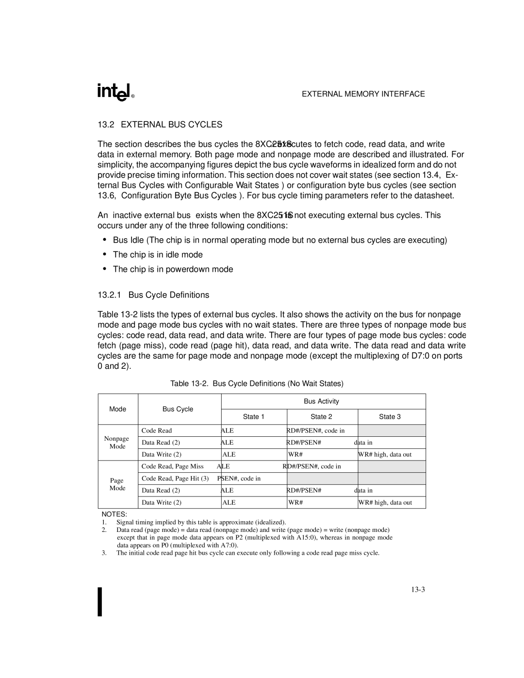
Bus Cycle Definitions No Wait States
Mode Bus Cycle Bus Activity State
External BUS Cycles
Bus Cycle Definitions
External Code Fetch Nonpage Mode
Nonpage Mode Bus Cycles
External Data Write Nonpage Mode
Mode Bus Cycles
External Code Fetch Page Mode
External Data Read Page Mode
Wait States
External BUS Cycles with Configurable Wait States
Extending RD#/WR#/PSEN#
External Code Fetch Nonpage Mode, One RD#/PSEN# Wait State
External BUS Cycles with REAL-TIME Wait States
Extending ALE
SA7H
Wcon
Xxxx XX00B Rtwce Rtwe
Real-time Wait Clock Enable Rtwce
Real-time WAIT# Enable Rtwe
Real-time Wait State Bus Cycle Diagrams
Wclk ALE WR#
Wclk ALE RD#/PSEN#
14. External Data Read Page Mode, RT Wait State
Nonpage Mode
Configuration Byte BUS Cycles
Port 0 and Port 2 Status
Port 0 and Port 2 Pin Status in Nonpage Mode
Port 0 and Port 2 Pin Status In Normal Operating Mode
Port Bit/16-bit Nonpage Mode
Port 0 and Port 2 Pin Status in Page Mode
Example 1 RD10 = 00, 18-bit Bus, External Flash and RAM
External Memory Design Examples
18. Address Space for Example
Example 2 RD10 = 01, 17-bit Bus, External Flash and RAM
19. Bus Diagram for Example 2 80C251SB in Page Mode
20. Address Space for Example
Example 3 RD10 = 01, 17-bit Bus, External RAM
22. Address Space for Example
PROM/EPROM
Example 4 RD10 = 10, 16-bit Bus, External RAM
24. Address Space for Example
An Application Requiring Fast Access to Data
An Application Requiring Fast Access to the Stack
Example 5 RD10 = 11, 16-bit Bus, External Eprom and RAM
25. Bus Diagram for Example 5 80C251SB in Nonpage Mode
RAM
Eprom
Example 6 RD10 = 11, 16-bit Bus, External Eprom and RAM
27. Bus Diagram for Example 6 80C251SB in Page Mode
Example 7 RD10 = 01, 17-bit Bus, External Flash
28. Bus Diagram for Example 7 80C251SB in Page Mode
Programming Verifying Nonvolatile Memory
Page
Chapter Programming and Verifying Nonvolatile Memory
Programming Considerations for On-chip Code Memory
Eprom Devices
General Setup
Programming and Verifying Modes
Port Address
Programming and Verifying Modes
RST PSEN#
PROG#
8XC251S
Programming Algorithm
Programmable Functions
Verify Algorithm
Programming Cycle
Lock Bit System
Configuration Bytes
Lock Bits Programmed Protection Type
Encryption Array
Signature Bytes
Lock Bit Function
Verifying the 83C251SA, SB, SP, SQ ROM
Contents of the Signature Bytes
Page
Instruction Set Reference
Page
Appendix a Instruction SET Reference
MCS
Notation for Instruction Operands
Table A-1. Notation for Register Operands
Register Notation
Table A-3. Notation for Immediate Addressing
Table A-2. Notation for Direct Addresses
Table A-4. Notation for Bit Addressing
Table A-6. Instructions for MCS 51 Microcontrollers
Opcode MAP and Supporting Tables
Bin A5x8 A5x9 A5xA A5xB A5xC A5xD A5xE A5xF Src
Table A-7. New Instructions for the MCS 251 Architecture
Byte
Table A-8. Data Instructions
Table A-9. High Nibble, Byte 0 of Data Instructions
Instruction
Table A-11. Byte 1 High Nibble for Bit Instructions
Table A-10. Bit Instructions
Bit Instruction
Trap
Table A-12. PUSH/POP Instructions
Table A-13. Control Instructions
Eret
Table A-14. Displacement/Extended MOVs
Table A-16. Encoding for INC/DEC
Table A-15. INC/DEC
Table A-17. Shifts
Instruction SET Summary
Execution Times for Instructions that Access the Port SFRs
Case
Table A-18. State Times to Access the Port SFRs
Instruction SET Reference
Subtract SUB dest,src
Instruction Summaries
Table A-19. Summary of Add and Subtract Instructions
Add ADD dest,src
CMP
Dest,src Binary Mode Source Mode
Table A-20. Summary of Compare Instructions
Compare CMP dest,src
DIV AB
Table A-21. Summary of Increment and Decrement Instructions
INC Dptr
MUL AB
RXX a
Table A-23. Summary of Logical Instructions
CLR a
CPL a
SRL
SRA
Swap
Move from External Mem Movx dest,src
Binary Mode Source Mode
Table A-24. Summary of Move Instructions
Move with Zero Extension Movz dest,src
Dir16,Rm Byte reg to dir addr 64K Dir16,WRj
Movc @A+DPTR
Movh
Movs
Movz
Push
Table A-25. Summary of Exchange, Push, and Pop Instructions
XCH
Xchd
Setb
Mnemonic Src,dest Binary Mode Source Mode
Table A-26. Summary of Bit Instructions
Move Bit from Carry MOV bit,CY
States Bytes
Table A-27. Summary of Control Instructions
NOP
JSG
Cjne
Djnz
Instruction Descriptions
Table A-28. Flag Symbols
ADD R1,R0
Variations ADD A,#data Binary Mode
Encoding Hex Code Operation
ADD dest,src Function Add
ADD
ADD Rm,#data Binary Mode
ADD DRkd,DRks Binary Mode Source Mode Bytes States Encoding
ADD WRj,dir8 Binary Mode
ADD WRj,#data16 Binary Mode
ADD DRk,#0data16 Binary Mode
ADD Rm,dir8 Binary Mode Source Mode Bytes States Encoding
WRj ← WRj + dir16
WRj ← WRj + dir8 ADD Rm,dir16 Binary Mode
Rm ← Rm + dir16 ADD WRj,dir16 Binary Mode
ADD Rm,@WRj Binary Mode Source Mode Bytes States Encoding
Flags
ADD Rm,@DRk Binary Mode Source Mode Bytes4 States4 Encoding
Variations Addc A,#data Binary Mode
Addc A,src Function
Addc
Ajmp Jmpadr
Ajmp addr11 Function Description Flags Example
ANL R1,R0
Variations ANL dir8,A Binary Mode Source Mode Bytes States
Hex Code Binary Mode = Encoding
ANL A,#data Binary Mode
ANL
ANL WRj,#data16 Binary Mode
ANL WRjd,WRjs Binary Mode Source Mode Bytes States Encoding
WRjd ← WRjd Λ WRjs
WRj ← WRj Λ dir8
Binary Mode = A5Encoding Source Mode = Encoding Operation
ANL WRj,dir8 Binary Mode
Rm ← Rm Λ dir16 ANL WRj,dir16 Binary Mode
ANL CY,src-bit
ANL Rm,@WRj Binary Mode Source Mode Bytes States Encoding
ANL Rm,@DRk Binary Mode
Hex Code Binary Mode = A5Encoding Source Mode = Encoding
MOV CY,P1.0
ANL CY,bit51 Binary Mode Source Mode Bytes States
ANL CY,/bit51 Binary Mode Source Mode Bytes States
ANL CY,bit Binary Mode Source Mode Bytes States
Wait Cjne A,P1,WAIT
ANL CY,/bit Binary Mode Source Mode Bytes States
Cjne dest,src,rel
Reqlow
Cjne A,dir8,rel
Variations Cjne A,#data,rel
Then
Else
Not Taken
Cjne Rn,#data,rel
CLR a
Bit51 ←
CLR
CLR CY
CMP R1,R0
CLR bit Binary Mode Source Mode Bytes States
Variations CMP Rmd,Rms Binary Mode
CMP dest,src Function
CMP
CMP WRjd,WRjs Binary Mode
WRjd WRjs CMP DRkd,DRks Binary Mode
DRkd DRks CMP Rm,#data Binary Mode
CMP Rm,dir8 Binary Mode
CMP WRj,#data16 Binary Mode
CMP Rm,dir16 Binary Mode
CMP WRj,dir8 Binary Mode
Rm dir16 CMP WRj,dir16 Binary Mode
CPL a
CMP Rm,@DRk Binary Mode Source Mode Bytes States Encoding
CPL CY
CPL
Operation CPL
CPL bit Binary Mode Source Mode Bytes States
DEC byte Function
Addc A,R3 DA a
DEC
DEC a
DEC dest,src Function Decrement
DEC Rn Bytes States Encoding
DEC WRj,#short
DIV R1,R5
DIV dest,src Function Divide
Location Contents
Binary Mode = A5Encoding Source Mode = Encoding
Djnz byte,rel-addr
DIV AB
Djnz Rn,rel
Djnz 40H,LABEL1 Djnz 50H,LABEL2 Djnz 60H,LABEL
Toggle CPL P1.7 Djnz R2,TOGGLE
Variations Djnz dir8,rel
Ecall Subrtn
Ecall dest Function
Ejmp dest Function
Ecall @DRk Binary Mode Source Mode Bytes States Encoding
Ejmp Jmpadr
Eret
Ejmp @DRk Binary Mode Source Mode Bytes States Encoding
INC Byte Function Increment
INC a
← a + INC dir8 Binary Mode
Dir8 ← dir8 + INC @Ri Binary Mode
INC @R0 INC R0
INC WRj,#short Binary Mode
INC Rn Binary Mode
INC dest,src Function Increment
WRj ← WRj + #short
JB bit51,rel JB bit,rel Function
Variations JB bit51,rel Binary Mode Source Mode
JB P1.2,LABEL1 JB ACC.2,LABEL2
JBC bit51,rel JBC bit,rel
Variations JBC bit51,rel Binary Mode Source Mode
JBC ACC.3,LABEL1 JBC ACC.2,LABEL2
Flags Example Bytes States Encoding
JBC bit,rel Binary Mode Source Mode
Hex Code in Binary Mode = Encoding Source Mode = Encoding
JC rel
JE LABEL1
JE rel Function
JG rel
JLE rel
Bytes States Encoding Binary Mode
Source Mode Not Taken
JG LABEL1
JNB bit51,rel JNB bit,rel
JMP @A+DPTR
JNB P1.3,LABEL1 JNB ACC.3,LABEL2
Variations JNB bit51,rel Binary Mode Source Mode
JNE LABEL1
JNC rel
JNC LABEL1 CPL CY JNC LABEL2
JNE rel
JNZ LABEL1 INC a JNZ LABEL2
JNZ rel
Jsge LABEL1
JSG rel
JSG LABEL1
Jsge rel
JSL LABEL1
JSL rel
Jsle LABEL1
Jsle rel
JZ rel
Lcall Subrtn
Lcall addr16 Binary Mode
JZ LABEL1 DEC a JZ LABEL2
Lcall dest Function
Ljmp dest Function
Lcall @WRj Binary Mode Source Mode Bytes States Encoding
Source Mode = Encoding Operation
Ljmp addr16 Binary Mode
Ljmp
MOV A,#data Binary Mode Source Mode Bytes States Encoding
PC ← addr.150
MOV
Ri ← #data MOV Rn,#data Binary Mode
Rn ← #data MOV dir8,dir8 Binary Mode
Operation MOV
Dir8 ← Ri MOV dir8,Rn Binary Mode
Dir8 ← dir8 MOV dir8,@Ri Binary Mode
Dir8 ← Rn MOV @Ri,dir8 Binary Mode
MOV Rn,dir8 Bytes States Encoding
MOV A,dir8 Binary Mode Source Mode Bytes States Encoding
← dir8 MOV A,@Ri Binary Mode
← Ri MOV A,Rn Binary Mode
Dir8 ← a MOV @Ri,A Binary Mode
MOV dir8,A Binary Mode Source Mode Bytes States Encoding
MOV Rn,A Binary Mode
MOV DRkd,DRks Binary Mode Source Mode Bytes States Encoding
Rmd ← Rms MOV WRjd,WRjs Binary Mode
MOV WRj,#data16 Binary Mode
WRj ← #data16 #data hi #data low
MOV WRj,dir16 Binary Mode
MOV WRj,dir8 Binary Mode Source Mode Bytes States Encoding
MOV DRk,dir8 Binary Mode Source Mode Bytes States Encoding
MOV Rm,dir16 Binary Mode Source Mode Bytes States Encoding
WRj ← dir16 MOV DRk,dir16 Binary Mode
MOV dir8,WRj Binary Mode
MOV WRjd,@WRjs Binary Mode
MOV WRj,@DRk Binary Mode
MOV dir8,Rm Binary Mode Source Mode Bytes States Encoding
Dir8 ← DRk MOV dir16,Rm Binary Mode
Dir8 ← WRj MOV dir8,DRk Binary Mode
Dir16 ← Rm MOV dir16,WRj Binary Mode
MOV @DRk,Rm Binary Mode Source Mode Bytes States Encoding
MOV @WRj,Rm Binary Mode Source Mode Bytes4 States4 Encoding
MOV @WRjd,WRjs Binary Mode
Rm ← WRj + dis MOV WRj,@WRj + dis16 Binary Mode
MOV @DRk,WRj Binary Mode
MOV @WRj + dis16,Rm Binary Mode
Rm ← DRk + dis MOV WRj,@DRk + dis24 Binary Mode
MOV @WRj + dis16,WRj Binary Mode
MOV @DRk + dis24,WRj Binary Mode
MOV @DRk + dis24,Rm Binary Mode
MOV dest-bit,src-bit
MOV bit,CY Binary Mode Source Mode Bytes States
Bit51 ← CY MOV CY,bit51 Binary Mode
MOV P1.3,CY MOV CY,P3.3 MOV P1.2,CY
MOV DPTR,#1234H
MOV CY,bit Binary Mode Source Mode Bytes States
Binary Mode Source Mode Bytes States Encoding
MOV DPTR,#data16
Movc A,@A+DPTR
Movc A,@A+base-reg Function
Relpc INC Movc @A+PC RET
Movc A,@A+PC
Movh DRk,#data16
Variations Movh DRk,#data16 Binary Mode
Movs WRj,Rm
Movx dest,src Function
Movx
← Dptr Movx A,@Ri Binary Mode
Movx A,@R1 Movx @R0,A
Movx A,@DPTR
Movz WRj,Rm
MUL R1,R0
MUL dest,src Function Multiply
MUL AB
MUL WRjd,WRjs Binary Mode Source Mode Bytes States Encoding
NOP Setb P2.7
NOP
Function Description Flags
Bytes States Encoding Hex Code Operation
ORL
Variations ORL dir8,A Binary Mode Source Mode Bytes States
ORL dir8,#data Binary Mode Source Mode Bytes States
ORL A,#data Binary Mode
ORL Rmd,Rms Binary Mode
ORL A,dir8 Binary Mode Source Mode Bytes States Encoding
← a V dir8 ORL A,@Ri Binary Mode
ORL A,Rn Binary Mode
WRjd←WRjd V WRjs
ORL WRjd,WRjs Binary Mode Source Mode Bytes States Encoding
ORL Rm,#data Binary Mode Source Mode Bytes States Encoding
ORL WRj,#data16 Binary Mode
Rm ← Rm V dir16 ORL WRj,dir16 Binary Mode
ORL Rm,dir8 Binary Mode
ORL WRj,dir8 Binary Mode
WRj ← WRj V dir8 ORL Rm,dir16 Binary Mode
ORL CY,src-bit
ORL Rm,@WRj Binary Mode Source Mode Bytes4 States3 Encoding
Rm ← Rm V WRj ORL Rm,@DRk Binary Mode
WRj ← WRj V dir16
ORL CY,bit Binary Mode Source Mode Bytes States
ORL CY,/bit51 Binary Mode Source Mode Bytes States
POP DPH POP DPL
ORL CY,/bit Binary Mode Source Mode Bytes States
POP dir8 Binary Mode
POP src Function
POP WRj Binary Mode
POP Rm Binary Mode
POP DRk Binary Mode
Operation Push
Push #data Binary Mode
Push dest Function
Push DPL Push DPH
Push WRj Binary Mode
Push #data16 Binary Mode
Operation RET
RET
Reti
RL a
RL a
RLC a
RR a
Example Bytes States Encoding
RLC a
RR a
Setb bit Function Set bit
RRC a
Flags Example Bytes States Encoding Hex Code Operation
RRC a
Setb CY
Setb
Sjmp Reladr
SLL Rm Binary Mode
SLL src
SRA src
SRL src
SRA WRj Binary Mode Source Mode Bytes States Encoding
SUB dest,src Function Subtract
Variations SUB Rmd,Rms Binary Mode
SUB R1,R0
SUB WRj,#data16
SUB DRkd,DRks Binary Mode Source Mode Bytes States Encoding
SUB
DRkd ← DRkd DRks
SUB WRj,dir8 Binary Mode
SUB DRk,#data16 Binary Mode
SUB Rm,dir8 Binary Mode Source Mode Bytes States
Hex Code Binary Mode = A5Encoding
SUB Rm,dir16
Rm ← Rm dir16 SUB WRj,dir16 Binary Mode
SUB Rm,@WRj Binary Mode Source Mode Bytes4 States3 Encoding
Rm ← Rm WRj SUB Rm,@DRk Binary Mode
Subb A,src-byte Function
Variations Subb A,#data Binary Mode
Subb A,R2
Subb
Swap a
Swap a
Trap
XCH A,byte
Binary Mode = Encoding Source Mode = Encoding
XCH A,@R0
Xchd A,@Ri Function
XCH A,@Ri Binary Mode Source Mode Bytes States Encoding
Operation XCH
XCH A,Rn Bytes States Encoding
XRL A,R0
XRL dir8,A Binary Mode Source Mode Bytes States
XRL A,#data
XRL A,dir8 Binary Mode Source Mode Bytes States Encoding
XRL
Dir8 ← dir8 ∀ a
XRL WRjd,WRjs
XRL A,Rn
XRL WRj,dir8
XRL Rm,#data
XRL WRj,#data16
XRL Rm,dir8
\XRL WRj,dir16
WRj ← WRj ∀ dir8 XRL Rm,dir16 Binary Mode
XRL Rm,@Wrj
XRL Rm,@Drk Binary Mode
Page
Signal Descriptions
Page
8XC251SQ
8XC251SA
8XC251SB
8XC251SP
Processor Control Name
Power & Ground Name
Address & Data Name
Plcc DIP
Component As mounted On PC board
8XC251SP 8XC251SQ
CEX20
DIP
PWR
GND
DIP WAIT#
Table B-3. Memory Signal Selections RD10
Page
Registers
Page
Appendix C Registers
Table C-1 XC251SA, SB, SP, SQ SFR Map
Table C-3. I/O Port SFRs
Table C-2. Core SFRs
Table C-4 Serial I/O SFRs
Table C-5. Timer/Counter and Watchdog Timer SFRs
SB9H
Table C-6. Programmable Counter Array PCA SFRs
Mnemonic Address
Table C-7. Register File
F0H
ACC
CCAP3H,L SFDH, Sedh
CCAPxH, CCAPxL x =
CCAP1H,L SFBH, Sebh
CCAP2H,L SFCH, Sech
CCAPM4 Sdeh
CCAPM1 Sdbh
CCAPM2 Sdch
CCAPM3 Sddh
SF9H SE9H
CH, CL
Cidl Wdte CPS1 CPS0 ECF
DPL
DPH
Dpxl
Global Interrupt Enable
IPH0 IPL0 Priority Level
IPL0
P1 Contents
P0 Contents
P1.70 Port 1 Register
P3 Contents
P2 Contents
P3.70 Port 3 Register
SMOD1 SMOD0 POF GF1 GF0 IDL
See -10 on
RCAP2L Scah
RCAP2H, RCAP2L
Slave Individual Address
Saddr
SADDR.70
SBUF.70
Saden
Sbuf
Data Sent/Received by Serial I/O Port
FE/SM0 SM1 SM2 REN TB8 RB8
SP.70 Stack Pointer
SP Contents
SPH
SPH Contents
SPH.70 Stack Pointer High
TF2 EXF2 Rclk Tclk EXEN2 TR2
T2OE Dcen
Xxxx XX00B
TF1 TR1 TF0 TR0 IE1 IT1 IE0 IT0
Address S89H Reset State
TH1, TL1
TH0, TL0
TH0 S8CH
TL0 S8AH
Rtwce Rtwe
TH2, TL2
TH2 Scdh
TL2 Scch
Wdtrst
Wdtrst Contents Write-only
WDTRST.70
Page
Glossary
Page
Glossary
Dptr
Eprom
LSB
Otprom
Uart
Word
Page
Index
Page
Index
Index-2
Index-3
Index-4
Index-5
Index-6
Index-7
Index-8
Index-9