Complete Hardware Guide for EX2200 Ethernet Switches
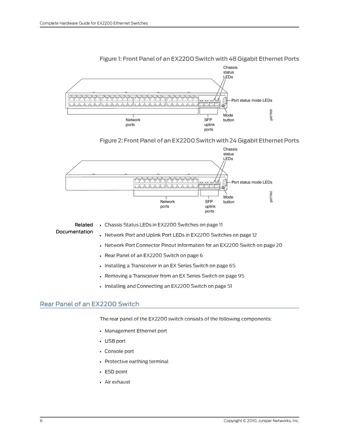
Figure 1: Front Panel of an EX2200 Switch with 48 Gigabit Ethernet Ports
Chassis status LEDs
0 | 1 | 2 3 | 4 5 | 6 7 | 8 9 | 10 11 | 12 13 | 14 | 15 | 1617 | 1819 | 2021 | 22 23 | 2425 | 2627 | 2829 | 3031 | 3233 | 34 35 | 3637 | 3839 | 4041 | 4243 | 4445 | 46 47 |
|
| SYS | ALM |
0 | 1 | 2 | 3 |
SPD | |
EN | Port status mode LEDs |
DX |
|
POE | |
|
|
|
|
| Mode |
|
|
|
|
| |
Network |
| SFP | button | ||
ports |
| uplink |
| ||
|
|
| ports |
| |
g027000
Figure 2: Front Panel of an EX2200 Switch with 24 Gigabit Ethernet Ports
Chassis status LEDs
0 | 1 | 2 3 | 4 5 | 6 7 | 8 9 | 10 11 | 12 13 | 14 | 15 | 1617 | 1819 | 2021 | 22 23 |
|
| SYS | ALM |
0 | 1 | 2 | 3 |
SPD | |
EN | Port status mode LEDs |
DX |
|
POE | |
|
|
|
|
| Mode |
|
|
|
|
| |
Network |
| SFP | button | ||
ports |
| uplink |
| ||
|
|
| ports |
| |
g027002
Related • Chassis Status LEDs in EX2200 Switches on page 11
Documentation
• Network Port and Uplink Port LEDs in EX2200 Switches on page 12
• Network Port Connector Pinout Information for an EX2200 Switch on page 20
• Rear Panel of an EX2200 Switch on page 6
• Installing a Transceiver in an EX Series Switch on page 65
• Removing a Transceiver from an EX Series Switch on page 95
• Installing and Connecting an EX2200 Switch on page 51
Rear Panel of an EX2200 Switch
The rear panel of the EX2200 switch consists of the following components:
•Management Ethernet port
•USB port
•Console port
•Protective earthing terminal
•ESD point
•Air exhaust
6 | Copyright © 2010, Juniper Networks, Inc. |