Chapter 2: Component Descriptions
The LEDs labeled Status LED in Figure 5 on page 12 and Figure 6 on page 12 indicate the status of one of the four port
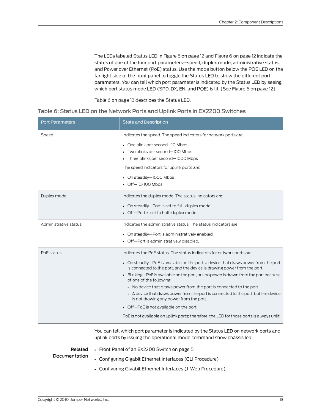
Table 6 on page 13 describes the Status LED.
Table 6: Status LED on the Network Ports and Uplink Ports in EX2200 Switches
Port Parameters | State and Description |
Speed | Indicates the speed. The speed indicators for network ports are: |
•One blink per
•Two blinks per
•Three blinks per
The speed indicators for uplink ports are:
| • | On |
| • | |
Duplex mode | Indicates the duplex mode. The status indicators are: | |
| • On | |
| • | |
Administrative status | Indicates the administrative status. The status indicators are: | |
| • On | |
| • | |
PoE status | Indicates the PoE status. The status indicators for network ports are: | |
| • On | |
|
| is connected to the port, and the device is drawing power from the port. |
| • | |
|
| of one of the following: |
|
| • No device that draws power from the port is connected to the port. |
|
| • A device that draws power from the port is connected to the port, but the device |
|
| is not drawing any power from the port. |
| • | |
| PoE is not available on uplink ports; therefore, the LED for those ports is always unlit. | |
You can tell which port parameter is indicated by the Status LED on network ports and uplink ports by issuing the operational mode command show chassis led.
Related • Front Panel of an EX2200 Switch on page 5
Documentation
• Configuring Gigabit Ethernet Interfaces (CLI Procedure)
• Configuring Gigabit Ethernet Interfaces
Copyright © 2010, Juniper Networks, Inc. | 13 |