Complete Hardware Guide for EX2200 Ethernet Switches
•Remove the switch from the shipping carton (see “Unpacking an EX2200 Switch” on page 52).
Ensure that you have the following parts and tools available:
•2
•1
•12
•6 mounting screws
•Hollow wall anchors rated to support up to 75 lb (34 kg) if you are not screwing the screws directly into wall studs (not provided)
•Phillips (+) screwdriver, number 2 (not provided)
To mount one or two switches on a wall:
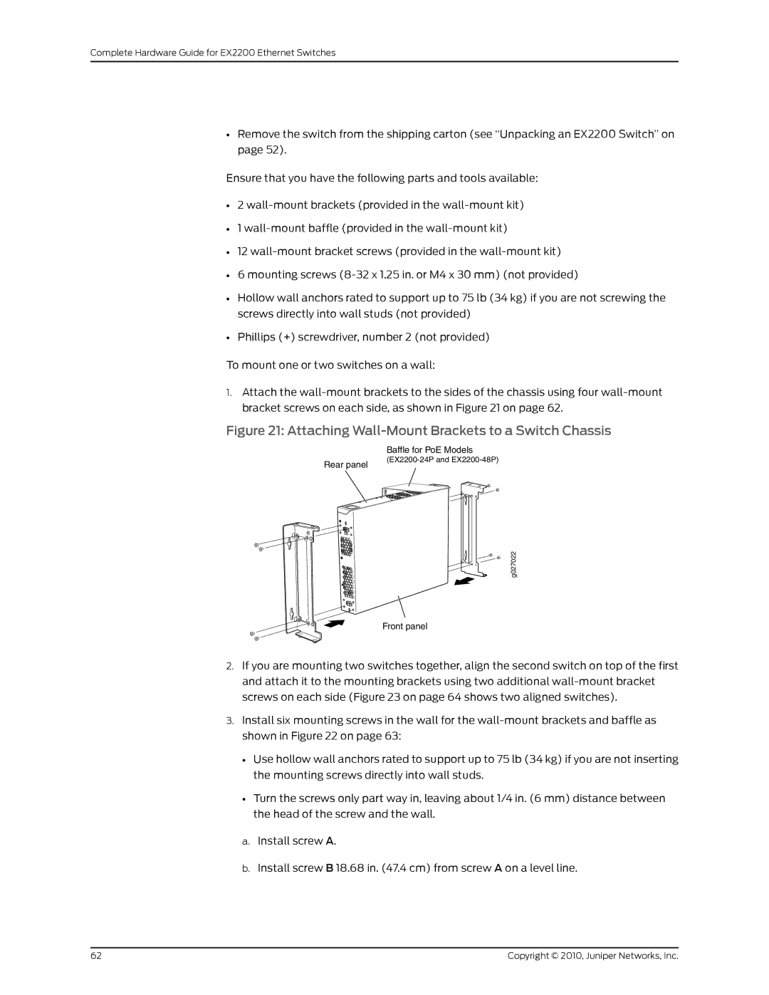
1.Attach the
Figure 21: Attaching Wall-Mount Brackets to a Switch Chassis
Rear panel
Baffle for PoE Models
g027022
Front panel
2.If you are mounting two switches together, align the second switch on top of the first and attach it to the mounting brackets using two additional
3.Install six mounting screws in the wall for the
•Use hollow wall anchors rated to support up to 75 lb (34 kg) if you are not inserting the mounting screws directly into wall studs.
•Turn the screws only part way in, leaving about 1/4 in. (6 mm) distance between the head of the screw and the wall.
a.Install screw A.
b.Install screw B 18.68 in. (47.4 cm) from screw A on a level line.
62 | Copyright © 2010, Juniper Networks, Inc. |