Complete Hardware Guide for EX2200 Ethernet Switches
•Connecting an EX Series Switch to a Management Console on page 76
Management Port Connector Pinout Information for an EX2200 Switch
The management port on an EX2200 switch uses an
The port uses an autosensing
Table 12 on page 22 provides the pinout information for the
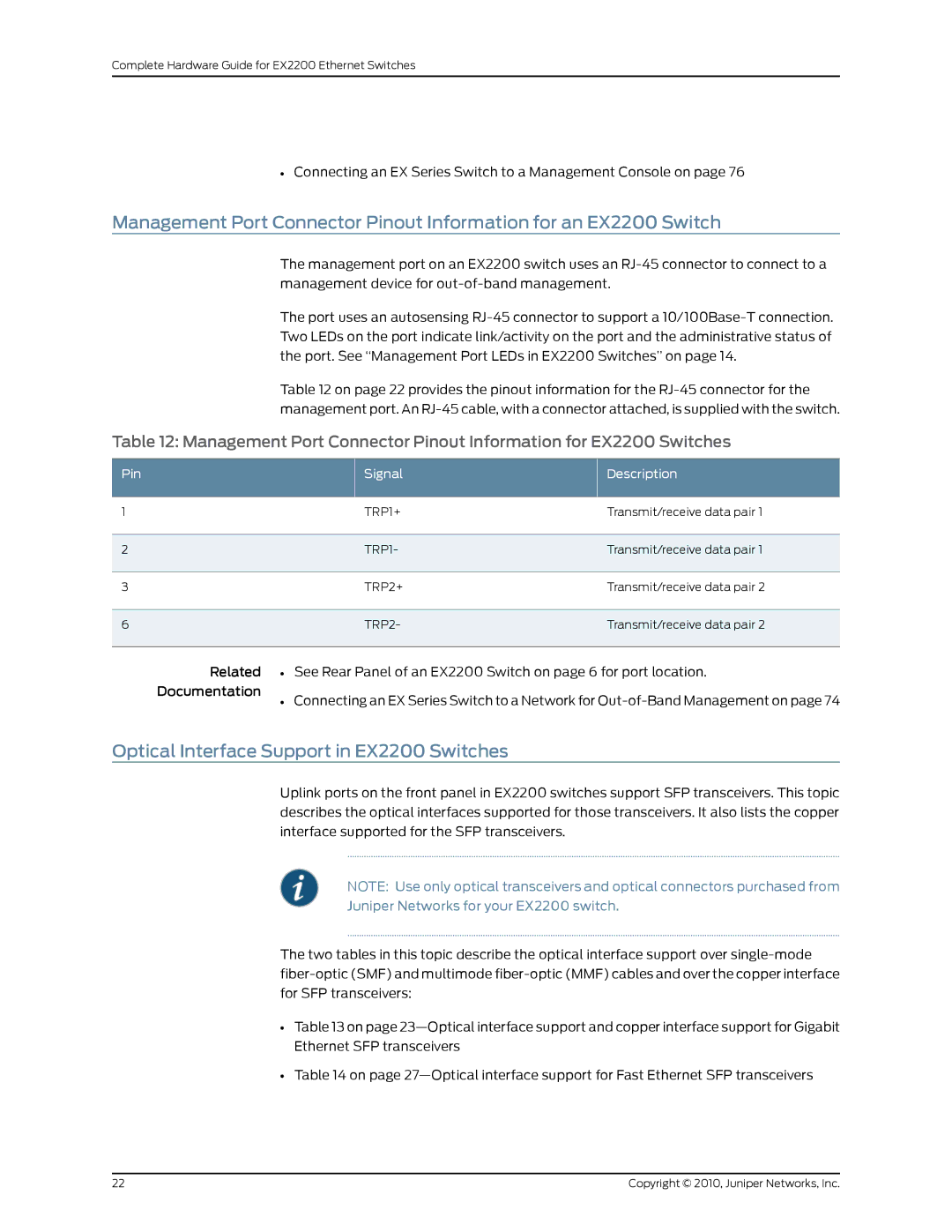
Table 12: Management Port Connector Pinout Information for EX2200 Switches
Pin | Signal | Description |
1 | TRP1+ | Transmit/receive data pair 1 |
2 | TRP1- | Transmit/receive data pair 1 |
3 | TRP2+ | Transmit/receive data pair 2 |
6 | TRP2- | Transmit/receive data pair 2 |
Related • See Rear Panel of an EX2200 Switch on page 6 for port location.
Documentation
• Connecting an EX Series Switch to a Network for
Optical Interface Support in EX2200 Switches
Uplink ports on the front panel in EX2200 switches support SFP transceivers. This topic describes the optical interfaces supported for those transceivers. It also lists the copper interface supported for the SFP transceivers.
NOTE: Use only optical transceivers and optical connectors purchased from
Juniper Networks for your EX2200 switch.
The two tables in this topic describe the optical interface support over
•Table 13 on page
•Table 14 on page
22 | Copyright © 2010, Juniper Networks, Inc. |