Complete Hardware Guide for EX2200 Ethernet Switches
Management Port LEDs in EX2200 Switches
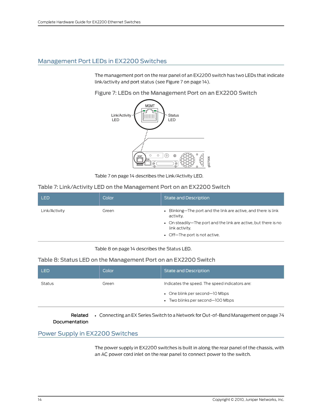
The management port on the rear panel of an EX2200 switch has two LEDs that indicate link/activity and port status (see Figure 7 on page 14).
Figure 7: LEDs on the Management Port on an EX2200 Switch
Link/Activity | Status |
LED | LED |
g027006
Table 7 on page 14 describes the Link/Activity LED.
Table 7: Link/Activity LED on the Management Port on an EX2200 Switch
LED | Color | State and Description |
Link/Activity | Green | • |
|
| activity. |
|
| • On |
|
| link activity. |
|
| • |
Table 8 on page 14 describes the Status LED.
Table 8: Status LED on the Management Port on an EX2200 Switch
LED | Color | State and Description | |
Status | Green | Indicates the speed. The speed indicators are: | |
|
| • | One blink per |
|
| • | Two blinks per |
Related | • Connecting an EX Series Switch to a Network for | ||
Documentation
Power Supply in EX2200 Switches
The power supply in EX2200 switches is built in along the rear panel of the chassis, with an AC power cord inlet on the rear panel to connect power to the switch.
14 | Copyright © 2010, Juniper Networks, Inc. |
