Chapter 5: Mounting and Clearance Requirements
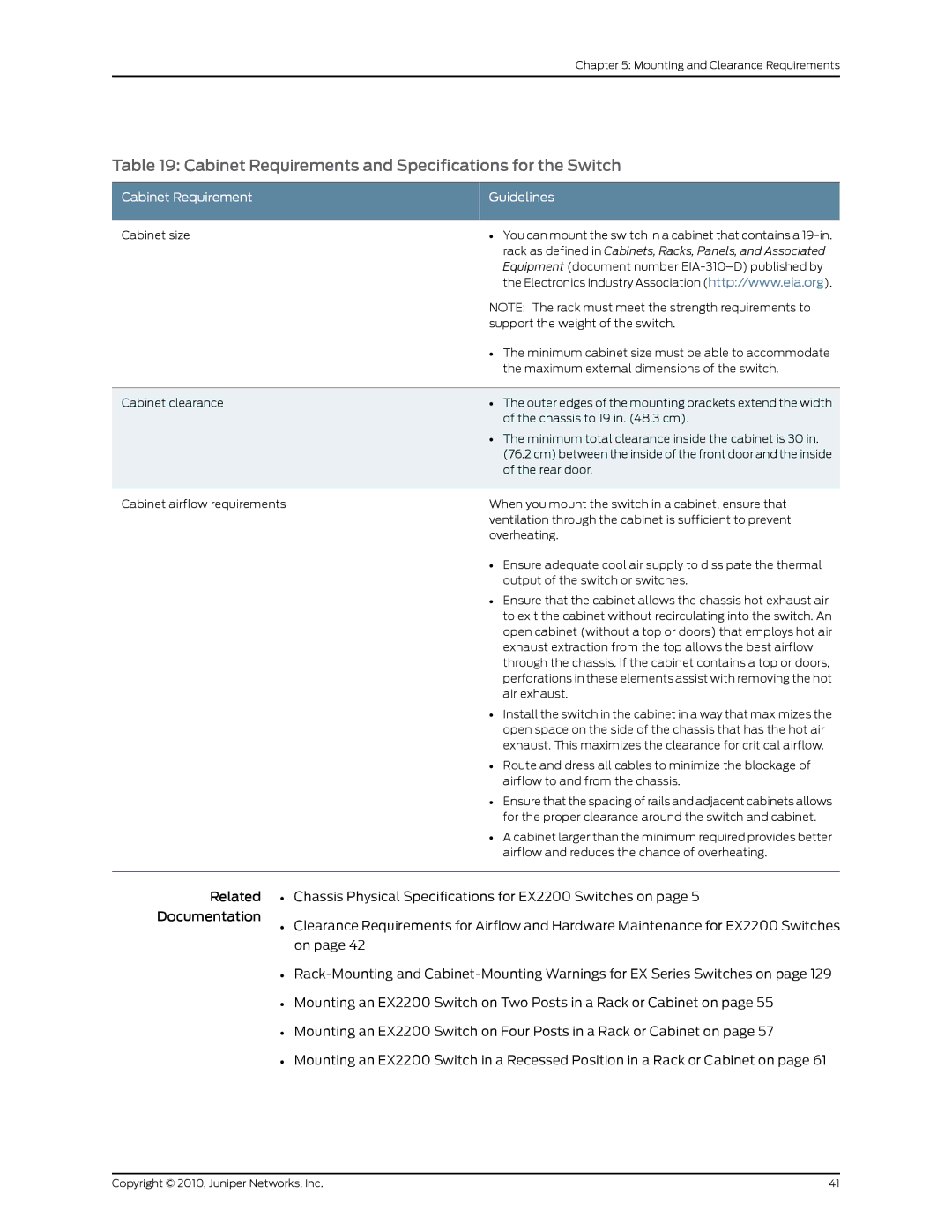
Table 19: Cabinet Requirements and Specifications for the Switch
Cabinet Requirement | Guidelines |
Cabinet size | • You can mount the switch in a cabinet that contains a |
| rack as defined in Cabinets, Racks, Panels, and Associated |
| Equipment (document number |
| the Electronics Industry Association (http://www.eia.org). |
| NOTE: The rack must meet the strength requirements to |
| support the weight of the switch. |
| • The minimum cabinet size must be able to accommodate |
| the maximum external dimensions of the switch. |
Cabinet clearance | • The outer edges of the mounting brackets extend the width |
| of the chassis to 19 in. (48.3 cm). |
| • The minimum total clearance inside the cabinet is 30 in. |
| (76.2 cm) between the inside of the front door and the inside |
| of the rear door. |
Cabinet airflow requirements | When you mount the switch in a cabinet, ensure that |
| ventilation through the cabinet is sufficient to prevent |
| overheating. |
| • Ensure adequate cool air supply to dissipate the thermal |
| output of the switch or switches. |
| • Ensure that the cabinet allows the chassis hot exhaust air |
| to exit the cabinet without recirculating into the switch. An |
| open cabinet (without a top or doors) that employs hot air |
| exhaust extraction from the top allows the best airflow |
| through the chassis. If the cabinet contains a top or doors, |
| perforations in these elements assist with removing the hot |
| air exhaust. |
| • Install the switch in the cabinet in a way that maximizes the |
| open space on the side of the chassis that has the hot air |
| exhaust. This maximizes the clearance for critical airflow. |
| • Route and dress all cables to minimize the blockage of |
| airflow to and from the chassis. |
| • Ensure that the spacing of rails and adjacent cabinets allows |
| for the proper clearance around the switch and cabinet. |
| • A cabinet larger than the minimum required provides better |
| airflow and reduces the chance of overheating. |
Related • | Chassis Physical Specifications for EX2200 Switches on page 5 |
Documentation | Clearance Requirements for Airflow and Hardware Maintenance for EX2200 Switches |
• | |
| on page 42 |
• | |
• Mounting an EX2200 Switch on Two Posts in a Rack or Cabinet on page 55
• Mounting an EX2200 Switch on Four Posts in a Rack or Cabinet on page 57
• Mounting an EX2200 Switch in a Recessed Position in a Rack or Cabinet on page 61
Copyright © 2010, Juniper Networks, Inc. | 41 |