Chapter 10: Connecting the Switch
Figure 29: Ethernet Cable Connector
To connect a device to a network for
1.Connect one end of the Ethernet cable to the management port (labeled MGMT) on the device.
For the location of the MGMT port on different devices:
•See “Rear Panel of an EX2200 Switch” on page 6.
•See Rear Panel of an EX3200 Switch.
•See Rear Panel of an EX4200 Switch.
•See Front Panel of an EX4500 Switch.
•See Switch Fabric and Routing Engine (SRE) Module in an EX8208 Switch.
•See Routing Engine (RE) Module in an EX8216 Switch.
•See Front Panel of an XRE200 External Routing Engine.
2.Connect the other end of the Ethernet cable to the management device.
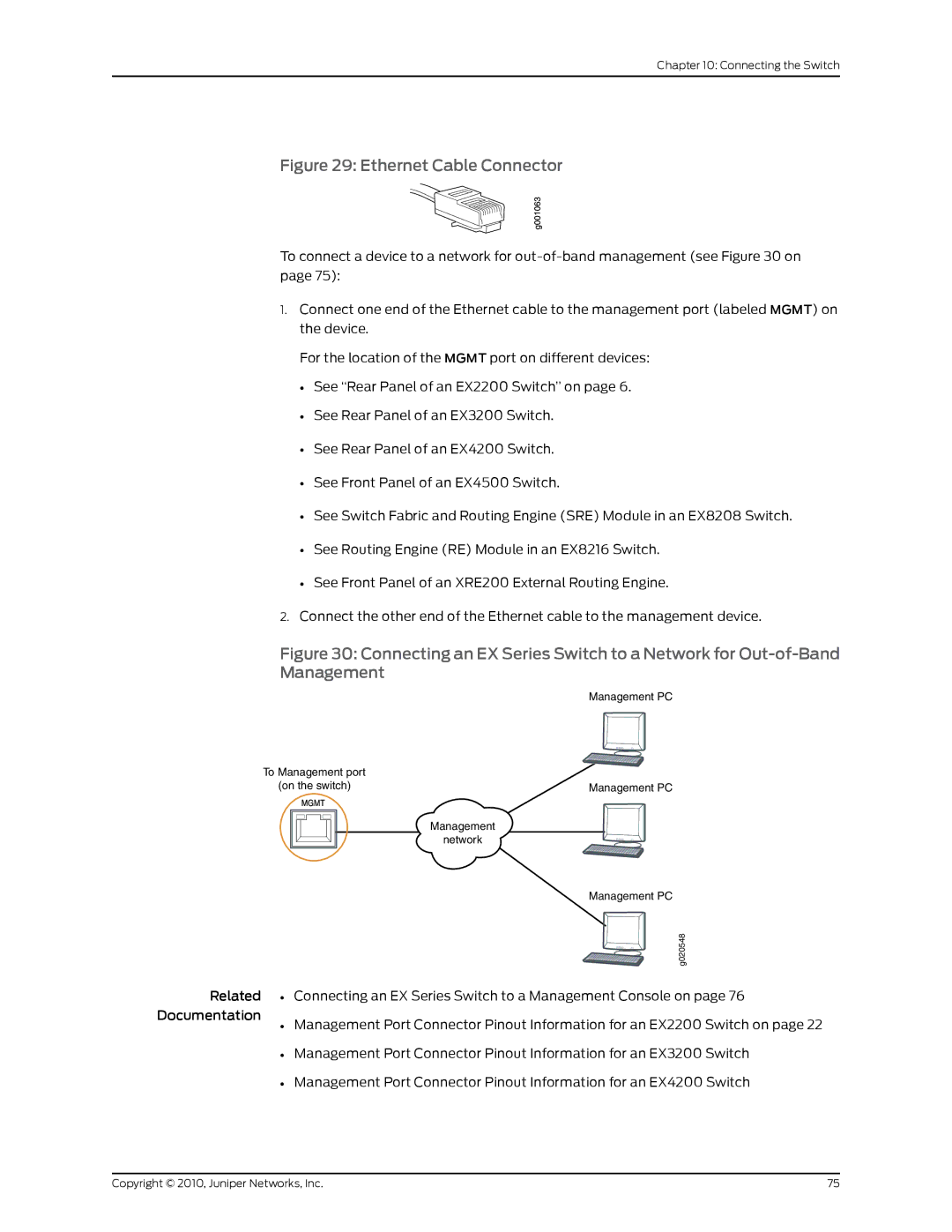
Figure 30: Connecting an EX Series Switch to a Network for Out-of-Band Management
Management PC
To Management port |
|
(on the switch) | Management PC |
Management
network
|
| Management PC |
|
| g020548 |
Related | • | Connecting an EX Series Switch to a Management Console on page 76 |
Documentation | • | Management Port Connector Pinout Information for an EX2200 Switch on page 22 |
|
• Management Port Connector Pinout Information for an EX3200 Switch
• Management Port Connector Pinout Information for an EX4200 Switch
Copyright © 2010, Juniper Networks, Inc. | 75 |