MTSX RSS |
|
|
|
|
|
|
|
|
|
|
|
|
|
| SERVICE | ||||||
4.2.1 TRANSMITTER ALIGNMENT MENU |
|
|
|
|
|
|
|
|
|
|
|
|
|
|
| ||||||
|
|
|
|
|
|
|
|
|
|
|
| F2 |
|
|
|
|
|
|
|
|
|
RSS LOCATION: |
|
| At the SERVICE MENU, press |
|
| . |
|
|
|
|
|
|
|
| |||||||
|
|
|
|
|
|
|
|
|
|
|
| ||||||||||
|
|
|
|
|
|
|
|
|
|
|
|
|
|
| |||||||
|
|
|
|
|
|
|
|
|
|
|
|
|
|
| |||||||
| MOTOROLA Radio Service Software |
|
|
|
|
| Select a Function F1 - F10. |
|
|
|
|
|
| ||||||||
| MTSX |
|
| Model: |
|
|
|
|
|
|
|
|
|
|
|
|
|
|
|
| |
| ...SERVICE:TRANSMITTER ALIGNMENT MENU |
|
|
|
|
|
|
|
|
|
|
|
|
|
|
| |||||
|
|
|
|
|
|
|
|
|
|
|
|
|
|
|
|
|
| ||||
|
|
|
|
|
|
|
|
|
|
|
|
|
|
|
| ||||||
|
|
|
|
|
|
|
|
|
|
|
|
|
| ||||||||
|
|
|
|
|
| TRANSMITTER ALIGNMENT MENU |
|
|
|
|
|
|
| ||||||||
|
| F1 | - | HELP |
|
|
|
|
|
|
|
|
|
|
|
|
|
|
|
| |
|
| F2 | - | Reference Oscillator |
|
|
|
|
|
|
|
|
|
|
|
|
|
|
| ||
|
| F3 | - | Tx Power |
|
|
|
|
|
|
|
|
|
|
|
|
|
|
|
| |
|
| F4 | - Tx Deviation Balance (Compensation) |
|
|
|
|
|
|
|
|
|
| ||||||||
|
| F5 | - | Tx Deviation Limit |
|
|
|
|
|
|
|
|
|
|
|
|
|
|
|
| |
|
| F6 | - Tx Deviation Limit: Reference |
|
|
|
|
|
|
|
|
|
| ||||||||
|
| F7 | - Tx VCO Crossover Frequency |
|
|
|
|
|
|
|
|
|
| ||||||||
|
| F8 | - | Secure Tx Deviation |
|
|
|
|
|
|
|
|
|
|
|
|
|
|
| ||
|
| F9 | - |
|
|
|
|
|
|
|
|
|
|
|
|
|
|
|
|
|
|
|
| F10 | - Exit, Return to Service Menu |
|
|
|
|
|
|
|
|
|
|
|
|
|
|
| |||
|
|
|
|
|
|
|
|
|
|
|
|
|
|
|
|
|
|
|
| ||
|
|
|
|
|
|
|
|
|
|
|
|
|
|
|
|
|
|
|
|
|
|
|
|
|
|
|
|
|
|
|
|
|
|
|
| ||||||||
|
| F1 | F2 |
| F3 | F4 | F5 | F6 | F7 | F8 | F9 | F10 |
| ||||||||
|
| HELP | REF | TX | DEV | DEV | REF | VCO | SECURE |
| EXIT |
| |||||||||
|
|
| OSC | PWR | BAL | LIMIT | ATTEN |
| DEV |
|
|
|
|
|
| ||||||
|
|
|
|
|
|
|
|
|
|
|
|
|
|
|
|
|
|
|
|
|
|
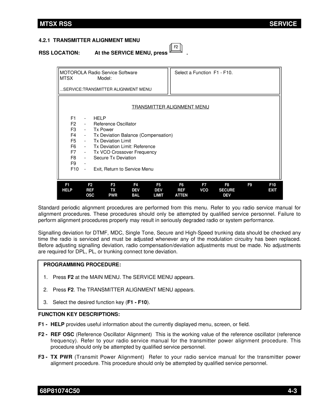
Standard periodic alignment procedures are performed from this menu. Refer to you radio service manual for alignment procedures. These procedures should only be attempted by qualified service personnel. Failure to perform alignment procedures properly may result in seriously degraded radio or system performance.
Signalling deviation for DTMF, MDC, Single Tone, Secure and
PROGRAMMING PROCEDURE:
1.Press F2 at the MAIN MENU. The SERVICE MENU appears.
2.Press F2. The TRANSMITTER ALIGNMENT MENU appears.
3.Select the desired function key (F1 - F10).
FUNCTION KEY DESCRIPTIONS:
F1 - HELP provides useful information about the currently displayed menu, screen, or field.
F2 - REF OSC (Reference Oscillator Alignment) This is the working value of the reference oscillator (reference frequency). Refer to your radio service manual for the transmitter power alignment procedure. This procedure should only be attempted by qualified service personnel.
F3 - TX PWR (Transmit Power Alignment) Refer to your radio service manual for the transmitter power alignment procedure. This procedure should only be attempted by qualified service personnel.
68P81074C50 | |
|
|
