Mechanical Installation & Cabling | MultiVOIP User Guide |
|
|
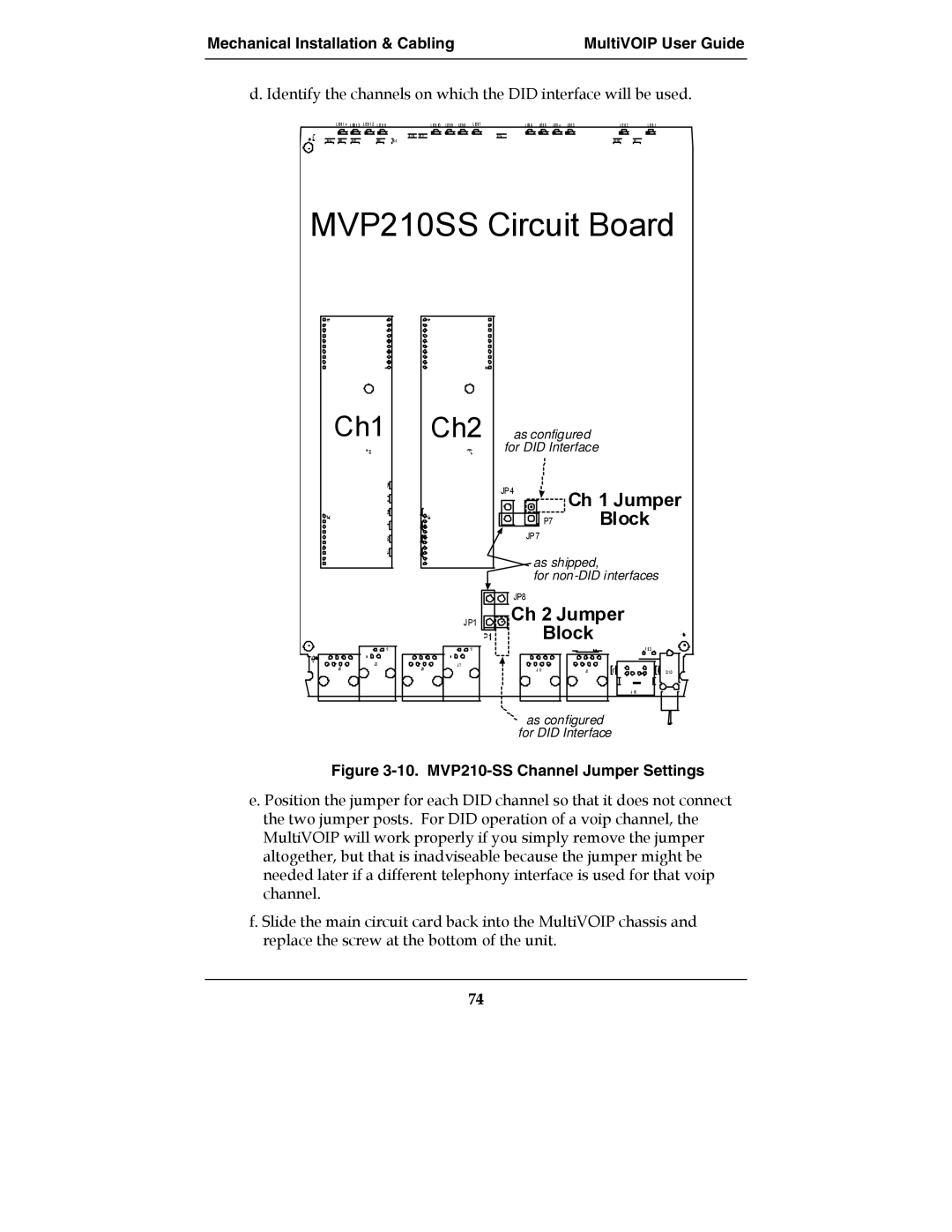
d. Identify the channels on which the DID interface will be used.
| L E D1 4 L ED1 3 L E D1 2 L E D11 |
| L E D10 LE D9 LE D8 | L E D7 | L ED6 | LE D5 | LE D4 | LE D3 | L E D2 | L E D1 | ||
|
|
|
| R 113 R7 2 |
|
| R 74 |
|
|
|
|
|
R114 | R58 | R 57 | R56 | R5 5 |
|
|
|
|
|
| R2 05 | R2 |
MVP210SS Circuit Board
Ch1 |
| Ch2 | as configured |
| ||
|
|
| for DID Interface |
| ||
|
|
| JP4 |
| Ch 1 Jumper | |
|
|
|
|
| ||
|
|
|
| JP7 | P7 | Block |
|
|
|
|
|
| |
|
|
|
| as shipped, |
| |
|
|
|
| for | ||
|
|
| JP8 |
|
|
|
|
| JP1 | Ch 2 Jumper | |||
|
|
|
|
| Block | F B 3 |
|
|
|
|
|
| |
J3 | J9 | J 7 |
| J 11 |
|
|
J5 |
|
| J1 | S 1 0 | ||
|
|
|
|
| ||
|
|
|
|
|
| J 15 |
as configured
for DID Interface
Figure 3-10. MVP210-SS Channel Jumper Settings
e. Position the jumper for each DID channel so that it does not connect the two jumper posts. For DID operation of a voip channel, the MultiVOIP will work properly if you simply remove the jumper altogether, but that is inadviseable because the jumper might be needed later if a different telephony interface is used for that voip channel.
f. Slide the main circuit card back into the MultiVOIP chassis and replace the screw at the bottom of the unit.
74