17 Canned Cycles for Drilling
The code of drilling:
For meanings of the codes see below.
Each code will be modal until an instruction G80 or a code is programmed, that belongs to G code group 1 (interpolation codes: G01, G02, G03, G33).
As long as the cycle state is on (instructions G73, G74, G76, G81,...G89), the modal cycle variables will be modal between drilling cycles of various types, too.
Initial point:
The initial point is the position of axis selected for drilling; it will be recorded
– when the cycle mode is set up. For example, in the case of
N1 G17 G90 G0 Z200
N2 G81 X0 Y0 Z50 R150
N3 X100 Y30 Z80
the position of initial point will be Z=200 in blocks N2 and N3, too.
– Or when a new drilling axis is selected. For example:
N1 G17 G90 G0 Z200 W50
N2 G81 X0 Y0 Z50 R150
N3 X100 Y30 W20 R25
position of start point is Z=200 in block N2 position of start point is W=50 in block N3
Programming of R is mandatory when the selection of drilling axis is changed, or else error message 3053 NO BOTTOM OR R POINT is returned.
Position of hole - Xp, Yp, Zp
Of the coordinate values entered, those in the selected plane will be taken for the position of the | |
hole. |
|
The values entered may be incremental or absolute ones, rectangular (Cartesian) or polar | |
coordinates in metric or inch units. |
|
The mirror image, coordinate system |
|
rotation and scaling commands are |
|
applicable to the coordinate values |
|
entered. |
|
The control moves to the position of hole |
|
in rapid traverse regardless of which code |
|
in group1 is in effect. |
|
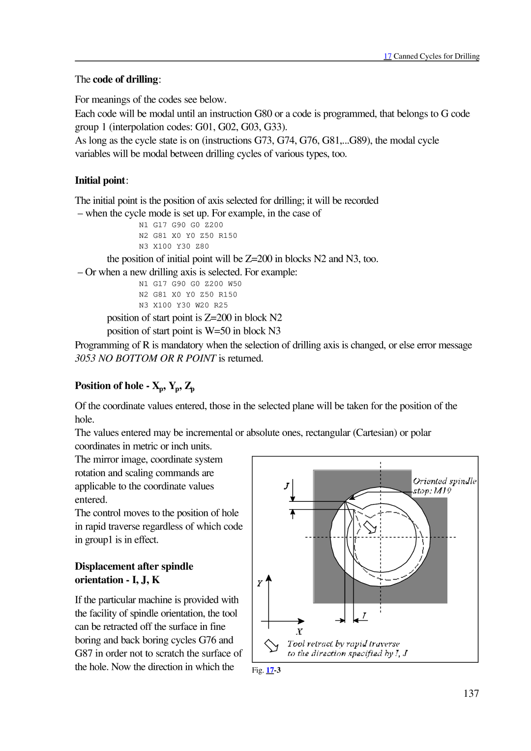
Displacement after spindle |
|
orientation - I, J, K |
|
If the particular machine is provided with |
|
the facility of spindle orientation, the tool |
|
can be retracted off the surface in fine |
|
boring and back boring cycles G76 and |
|
G87 in order not to scratch the surface of |
|
the hole. Now the direction in which the | Fig. |
137
