14 The Tool Compensation
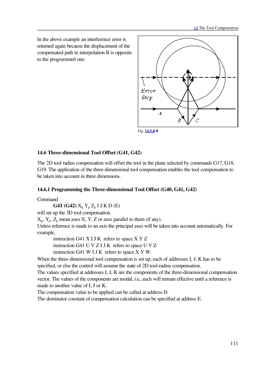
In the above example an interference error is returned again because the displacement of the compensated path in interpolation B is opposite to the programmed one.
Fig. |
14.6 Three-dimensional Tool Offset (G41, G42)
The 2D tool radius compensation will offset the tool in the plane selected by commands G17, G18, G19. The application of the
14.6.1 Programming the Three-dimensional Tool Offset (G40, G41, G42)
Command
G41 (G42) Xp Yp Zp I J K D (E) will set up the 3D tool compensation.
Xp, Yp, Zp mean axes X, Y, Z or axes parallel to them (if any).
Unless reference is made to an axis the principal axes will be taken into account automatically. For example,
instruction G41 X I J K refers to space X Y Z instruction G41 U V Z I J K refers to space U V Z instruction G41 W I J K refers to space X Y W.
When the
The values specified at addresses I, J, K are the components of the
The compensation value to be applied can be called at address D.
The dominator constant of compensation calculation can be specified at address E.
111