9 Coordinate Systems, Plane Selection
9.1.1 Setting the Machine Coordinate system
After a reference point return, the machine coordinate system can be set in parameters. The distance of the reference point, calculated from the origin of the machine coordinate system, has to be written for the parameter.
9.1.2 Positioning in the Machine Coordinate System (G53)
Instruction G53 v
will move the tool to the position of v coordinate in the machine coordinate system.
–Regardless of states G90, G91, coordinates v are always treated as absolute coordinates,
–operator I is ineffective when put behind the address of a coordinate,
–similar to instruction G00, the movements are performed in rapid traverse,
–the positioning is carried out invariably with the selected tool length compensations taken into
account.
A G53 instruction can be executed after a reference point return only. G53 is a
9.2 Work Coordinate Systems
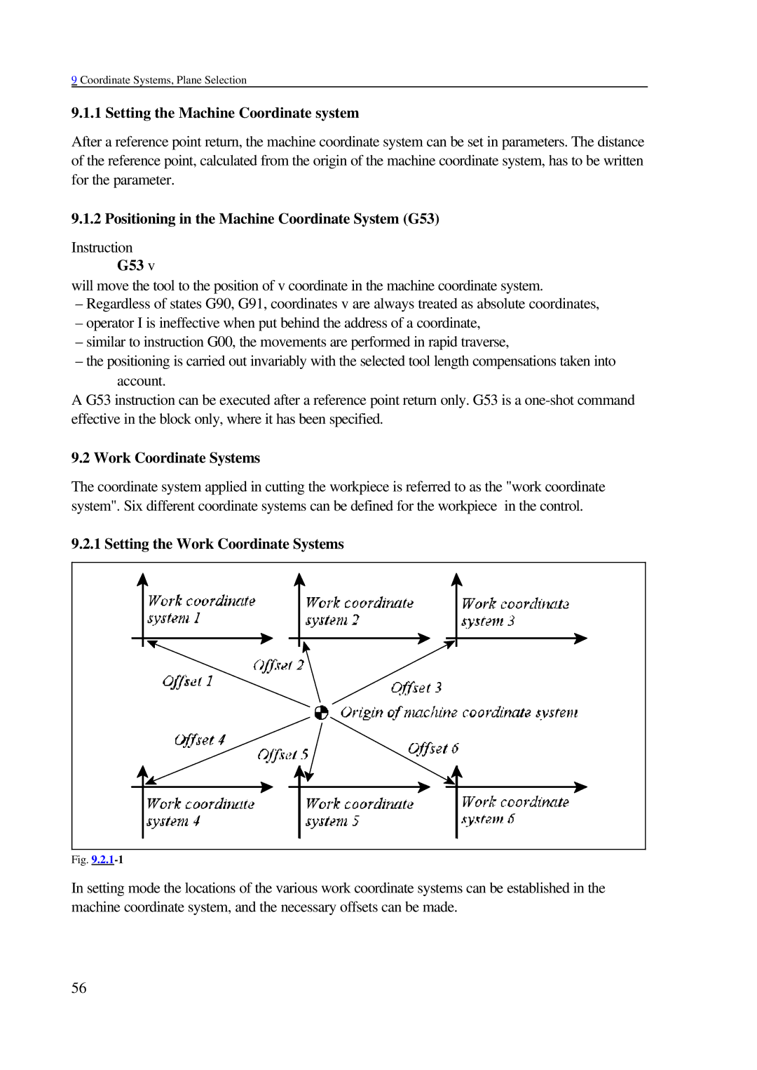
The coordinate system applied in cutting the workpiece is referred to as the "work coordinate system". Six different coordinate systems can be defined for the workpiece in the control.
9.2.1 Setting the Work Coordinate Systems
Fig. |
In setting mode the locations of the various work coordinate systems can be established in the machine coordinate system, and the necessary offsets can be made.
56