4.7Cylindrical Interpolation (G7.1)
Application of tool radius compensation in case of cylindrical interpolation Commands G41, G42 can be used in the usual manner in the
–
–Should G41 or G42 be switched on in cylindrical interpolation mode, G40 must be programmed before switching cylindrical interpolation off (command G7.1 Q0).
Programming restrictions in the course of cylindrical interpolation
The following commands are not available in the
–plane selection: G17, G18, G19,
–coordinate transformations: G52, G92,
–work coordinate system change: G54, ..., G59,
–positioning in machine coordinate system: G53,
–circular interpolation by giving circle center (I, J, K),
–drilling cycles.
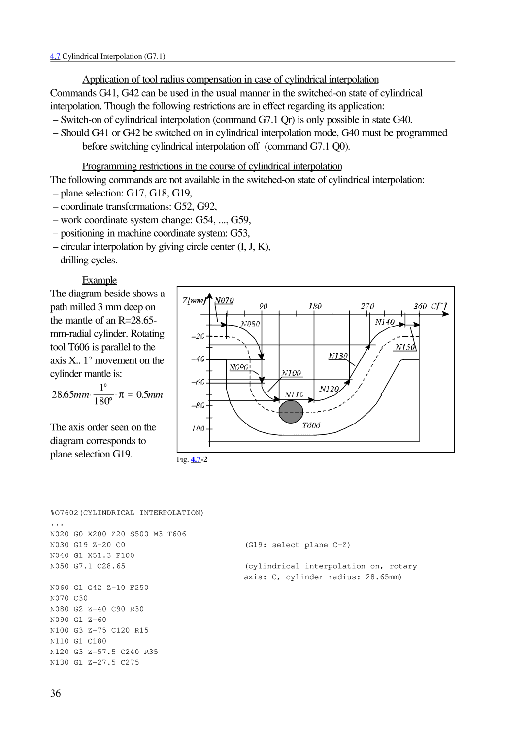
Example
The diagram beside shows a path milled 3 mm deep on the mantle of an R=28.65-
1°
28.65mm⋅ 180° ⋅ π = 0.5mm
The axis order seen on the diagram corresponds to plane selection G19.
Fig. |
%O7602(CYLINDRICAL INTERPOLATION)
... |
|
|
|
|
|
N020 | G0 | X200 | Z20 | S500 | M3 T606 |
N030 | G19 |
| (G19: select plane | ||
N040 | G1 | X51.3 F100 |
| ||
N050 | G7.1 C28.65 |
| (cylindrical interpolation on, rotary | ||
|
|
|
|
| axis: C, cylinder radius: 28.65mm) |
N060 | G1 | G42 | F250 |
| |
N070 | C30 |
|
|
| |
N080 | G2 | R30 |
| ||
N090 | G1 |
|
|
| |
N100 | G3 |
| |||
N110 | G1 | C180 |
|
|
|
N120 | G3 | ||||
N130 | G1 |
| |||
36