14 The Tool Compensation
14 The Tool Compensation
14.1 Referring to Tool Compensation Values (H and D)
Reference can be made to
tool length compensation at address H, tool radius compensation at address D.
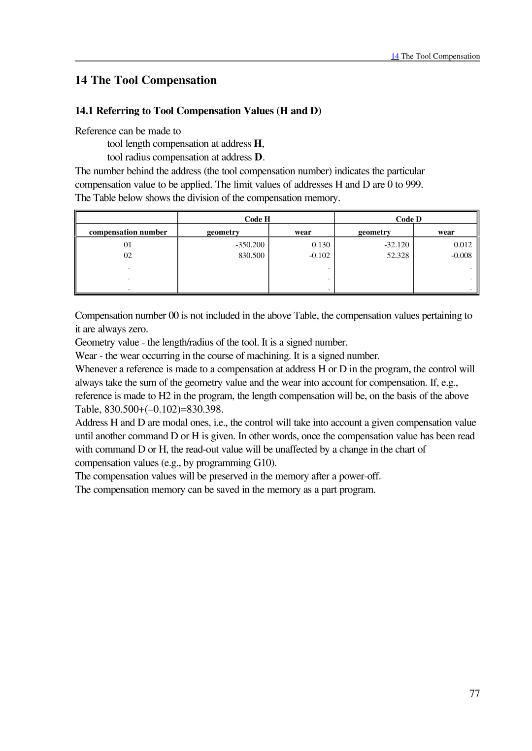
The number behind the address (the tool compensation number) indicates the particular compensation value to be applied. The limit values of addresses H and D are 0 to 999. The Table below shows the division of the compensation memory.
|
|
|
|
|
|
|
|
| Code H |
| Code D |
|
| ||
compensation number | geometry |
| wear | geometry |
| wear |
|
01 |
| 0.130 |
| 0.012 |
| ||
02 | 830.500 |
| 52.328 |
|
| ||
. |
|
| . |
|
| . |
|
. |
|
| . |
|
| . |
|
. |
|
| . |
|
| . |
|
|
|
|
|
|
|
|
|
Compensation number 00 is not included in the above Table, the compensation values pertaining to it are always zero.
Geometry value - the length/radius of the tool. It is a signed number.
Wear - the wear occurring in the course of machining. It is a signed number.
Whenever a reference is made to a compensation at address H or D in the program, the control will always take the sum of the geometry value and the wear into account for compensation. If, e.g., reference is made to H2 in the program, the length compensation will be, on the basis of the above Table,
Address H and D are modal ones, i.e., the control will take into account a given compensation value until another command D or H is given. In other words, once the compensation value has been read with command D or H, the
The compensation values will be preserved in the memory after a
77
