NCT 99M NCT 2000M
Manufactured by NCT Automation kft
Contents
Dwell G04
100
Page
180
Page
Part Program
Introduction
O1234PROGRAM NAMEs/1N12345G1X0Y...sG2Z5...s....s N1G40...M2s
Block
Fundamental Terms
Introduction
G90 X50 Y80 Z40
M3 M8
Introduction
Names of axes
Controlled Axes
Unit and Increment System of Axes
IS-A
Preparatory Functions G codes
116
141
G01 v F
Interpolation
Positioning G00
Linear Interpolation G01
G01 X100 Y80 F150
Circular and Spiral Interpolation G02, G03
Case
G03 X0 Y100
Helical Interpolation G02, G03
G17 G03 X0 Y100 Z20 R100 F150
Equal Lead Thread Cutting G33
An example of programming a thread-cutting
G12.1
Polar Coordinate Interpolation G12.1, G13.1
G13.1
Polar Coordinate Interpolation G12.1, G13.1
O7500POLAR Coordinate Interpolation
Direction X on rotary axis C
Cylindrical Interpolation G7.1
28.65mm⋅ 180 ⋅ π = 0.5mm
Cylindrical Interpolation G7.1
Coordinate Data
Polar Coordinates Data Command G15, G16
Absolute and Incremental Programming G90, G91, Operator
G90 G16 G01 X100 Y60 F180
Inch/Metric Conversion G20, G21
Specification and Value Range of Coordinate Data
Rotary Axis Roll-over
ROLLOVENC=1
Rollovenc =1
Feed in rapid travers
Feed
Cutting Feed Rate
Feed per Minute G94 and Feed per Revolution G95
Clamping the Cutting Feed
Automatic Acceleration/Deceleration
Feed Control Functions
Exact Stop Mode G61
Exact Stop G09
Override and Stop Inhibit Tapping Mode G63
Continuous Cutting Mode G64
Automatic Corner Override G62
Internal Circular Cutting Override
Dwell G04
Automatic Reference Point Return G28
Reference Point
Automatic Return from the Reference Point G29
Automatic return to reference points 2nd, 3rd, 4th G30
G90 G30 P1 X500 Y200 G29 X700 Y150
Machine Coordinate System
Coordinate Systems, Plane Selection
Work Coordinate Systems
Setting the Machine Coordinate system
Setting the Work Coordinate Systems
Positioning in the Machine Coordinate System G53
Selecting the Work Coordinate System
Creating a New Work Coordinate System G92
Programmed Setting of the Work Zero Point Offset
Local Coordinate System
G90 G52 X60 Y40
Plane Selection G17, G18, G19
Codes
Spindle Function
Spindle Speed Command code S
Programming of Constant Surface Speed Control
G96 S
10.2.1Constant Surface Speed Control Command G96, G97
Constant Surface Speed Clamp G92
Oriented Spindle Stop
Selecting an Axis for Constant Surface Speed Control
G96 P. Interpretation of address P
Spindle Position Feedback
G25
Spindle Positioning Indexing
Spindle Speed Fluctuation Detection G25, G26
G26
Spindle Function
Spindle Function
Tool Function
Tool Select Command Code T
Program Format for Tool Number Programming
Tool Function
Miscellaneous Functions Codes M
Miscellaneous and Auxiliary Functions
Sequence of Execution of Various Functions
Auxiliary Function Codes A, B, C
Part Program Configuration
Return from a Sub-program
M98 P.... L
M99
M99 P
Jump within the Main Program
Referring to Tool Compensation Values H and D
Tool Compensation
Limit values of geometry and wear
G44 compensation
Tool Length Compensation G43, G44, G49
G43 q H or G44 q H
G43 + compensation
Tool Offset G45...G48
Tool Compensation
Tool Compensation
Tool Compensation
Cutter Compensation G38, G39, G40, G41, G42
G41
Tool Compensation
Start up of Cutter Compensation
Tool Compensation
G91 G17 G40 N110 G42 G1 X-80 Y60 I50 J70 D1 N120
N10 G40 G17 G0 X0 Y0 N15 G91 G42 D1 N20 G1 N25 X30 Y60
Rules of Cutter Compensation in Offset Mode
Tool Compensation
G91 G17 G42 N110 G1 X40 Y50 N120 N130 N140 X50 Y-20
Canceling of Offset Mode
G91 G17 G42 N100 G1 X50 Y60 N110 G40 X70 Y-60 I100 J-20
G42 G17 G91 N110 G1 X80 Y40 N120 G40 N130 X-70 Y20
Change of Offset Direction While in the Offset Mode
Tool Compensation
Programming Corner Arcs G39
Programming Vector Hold G38
14.5.6
When two interpolations outside of the selected plane
G17 G91 N110 G41 G0 X50 Y70 D1 N120 G1 Z-40 N130 Y40
103
Tool Compensation
Tool Compensation
Tool Compensation
Interferences in Cutter Compensation
Tool Compensation
Tool Compensation
Tool Compensation
Programming the Three-dimensional Tool Offset G40, G41, G42
Three-dimensional Tool Offset G41, G42
G40 or D00
Three-dimensional Offset Vector
Tool Compensation
Coordinate System Rotation G68, G69
Special Transformations
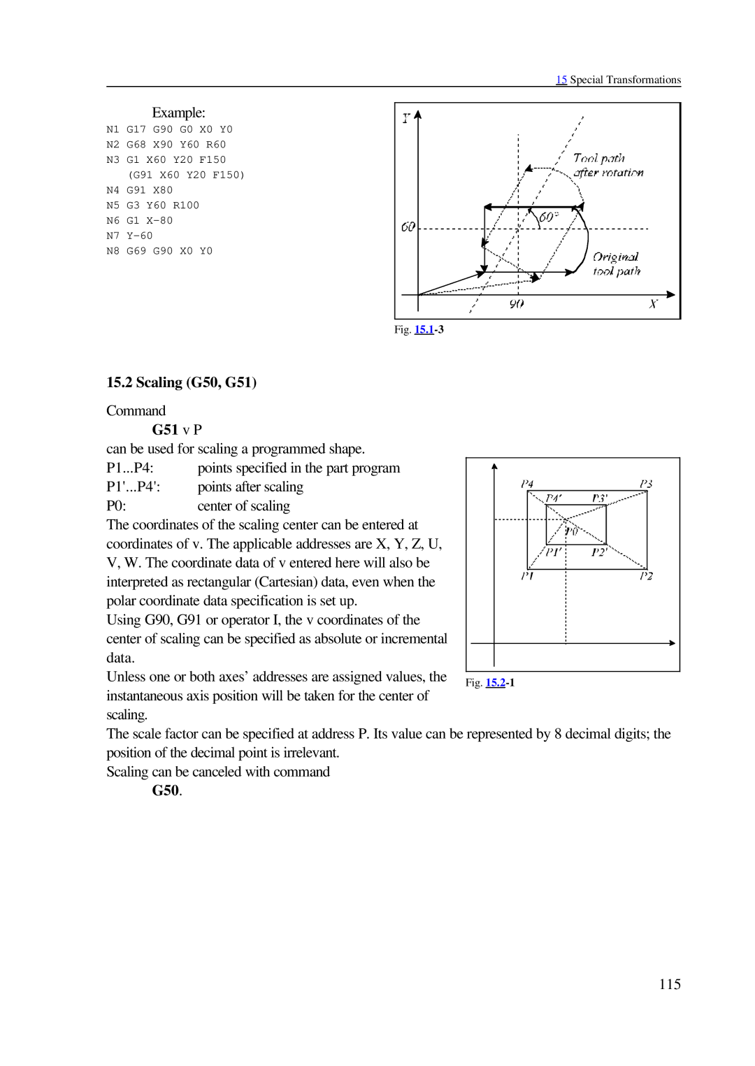
G51 v P
Scaling G50, G51
G51.1
Programmable Mirror Image G50.1, G51.1
Rotation-scaling Scaling-rotation
Rules of Programming Special Transformations
Special Transformations
Programming Chamfer and Corner Round
Automatic Geometric Calculations
Specifying Straight Line with Angle
Is equivalent to the block below
Intersection Calculations in the Selected Plane
Linear-linear Intersection
Automatic Geometric Calculations
Automatic Geometric Calculations
Linear-circular Intersection
127
Let us see the following example
Circular-linear Intersection
Let us see an example
Circular-circular Intersection
132
Let us see the following example
Chaining of Intersection Calculations
Canned Cycles for Drilling
136
Position of hole Xp, Yp, Zp
Displacement after spindle Orientation I, J, K
Code of drilling
Initial point
Data of drilling
Examples of modal drilling codes and cycle variables
Examples of using cycle repetitions
Canned Cycles for Drilling
Counter Tapping Cycle G74
Fine Boring Cycle G76
Drilling, Spot Boring Cycle G81
Canned Cycle Cancel G80
Drilling, Counter Boring Cycle G82
Peck Drilling Cycle G83
Tapping Cycle G84
With G98, rapid-traverse retraction to the initial point
= distance between point R and point Z
Canned Cycles for Drilling
Boring Cycle G85
Boring Cycle Tool Retraction with Rapid Traverse G86
Boring Cycle, Manual Operation at Bottom Point
Boring Cycle/Back Boring Cycle G87
Back Boring Cycle
Boring Cycle Manual Operation on the Bottom Point G88
Canned Cycles for Drilling
Canned Cycles for Drilling
Skip Function G31
Measurement Functions
Automatic Tool Length Measurement G37
Measurement Functions
Programmable Stroke Check G22, G23
Safety Functions
G23
Parametric Overtravel Positions
Stroke Check Before Movement
Simple Macro Call G65
Custom Macro
C I1 J1 K1 I2 J2 K2 ... I10 J10 K10
G67
Particular number. For example
Illegal G Code
Macro Modal Call From Each Block G66.1
Custom Macro Call Using G Code
Subprogram Call with M Code
Custom Macro Call Using M Code
#198=s
Subprogram Call with T Code
#199=t
Subprogram Call with S Code
Multiple Calls
Level of call
Referring to a variable
Format of Custom Macro Body
Variables of the Programming Language
Identification of a Variable
Numerical Format of Variables
Vacant Variables
Local Variables #1 through #33
Types of Variables
Common Variables #100 through #199, #500 through #599
System Variables
Interface input signals #1000-#1015, #1032
Interface output signals #1100-#1115, #1132
Tool compensation values #10001 through #13999
Work zero-point offsets #5201 through #5328
Suppression of block-by-block execution #3003
Alarm #3000
Millisecond timer #3001
Main time timer #3002
Stop with message #3006
Suppression of stop button, feed override, exact stop #3004
Mirror image status #3007
Modal information #4001 through #4130, #4201 through #4330
Instantaneous positions in the work coordinate system
Tool-length compensation
Skip signal position
Instructions of the Programming Language
Servo lag
Definition, Substitution #i = #j
Logical sum, or #i = #j or #k
Arithmetic Operations and Functions
Single-operand minus #i = #j The code of the operation is
Subtraction #i = #j #k
Arc cosine #i = Acos #j
Square root #i = Sqrt #j
Logarithm natural #i = LN #j
Arc tangent #i = Atan #j
Absolute value #i = ABS #j
Unconditional Divergence GOTOn
Logical Operations
Conditional Instruction IFconditional expression then
Conditional Divergence IFconditional expression GOTOn
Instructions DOm and ENDm must be put in pairs
Pairs DOm ... ENDm may not be overlapped
Decimal data print output
Data Output Commands
Periphery open
Binary data print output
Decimal data output Dprnt
Characters to be output are
194
NC and Macro Instructions
Closing a peripheral PCLOSn
Execution of NC and Macro Instructions in Time
Sbstm =0
Displaying Macros and Sub-programs in Automatic Mode
Pocket-milling Macro Cycle
Degenerated cases of cavity milling
Error messages in the course of pocket milling
Custom Macro
202
15 , 72
Index in Alphabetical Order
Index in Alphabetical Order
Index in Alphabetical Order
Index in Alphabetical Order