17 Canned Cycles for Drilling
where Xp is axis X or the one parallel to it Yp is axis Y or the one parallel to it Zp is axis Z or the one parallel to it.
Axes U, V, W are regarded to be parallel ones when they are defined in parameters.
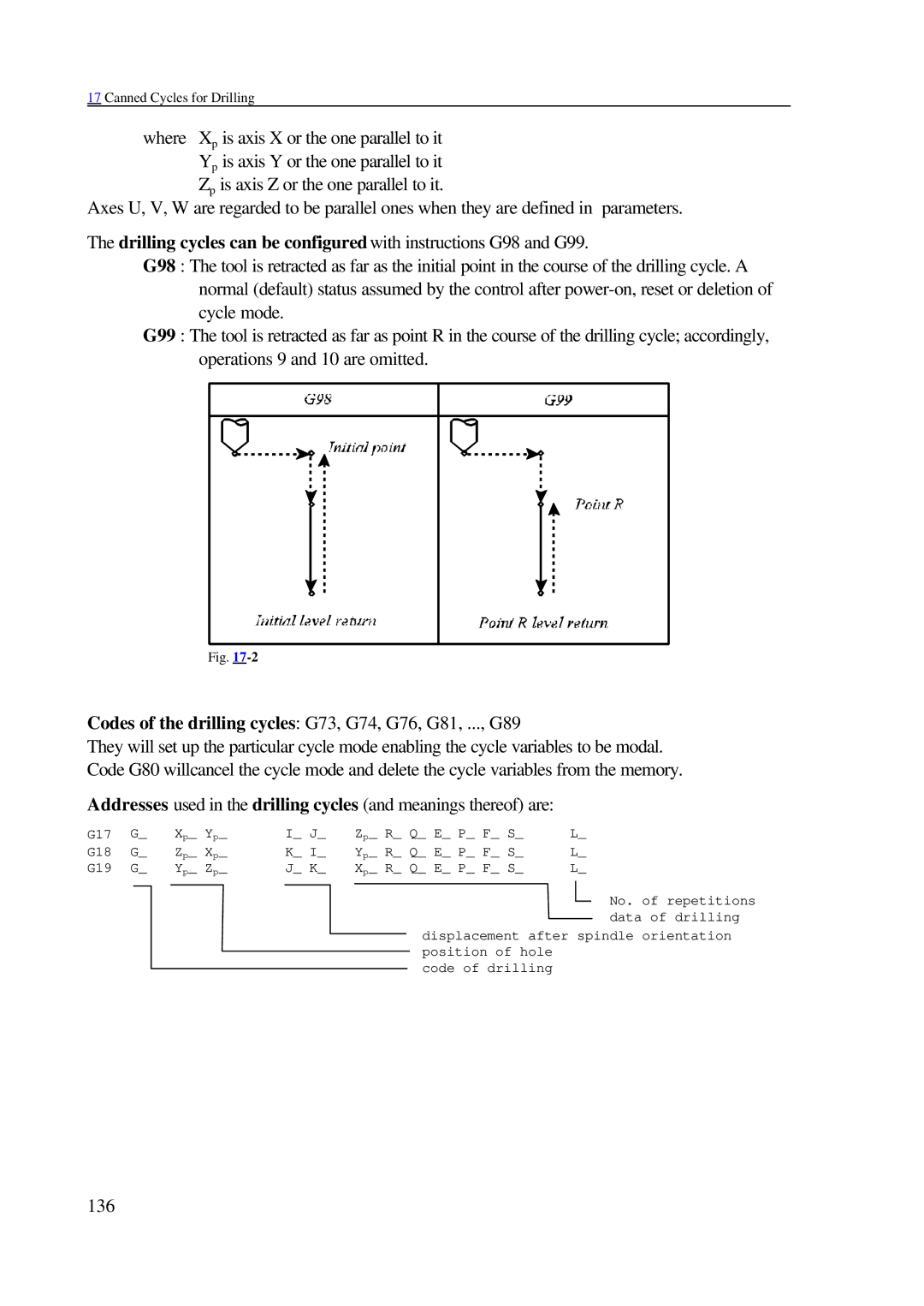
The drilling cycles can be configured with instructions G98 and G99.
G98 : The tool is retracted as far as the initial point in the course of the drilling cycle. A normal (default) status assumed by the control after
G99 : The tool is retracted as far as point R in the course of the drilling cycle; accordingly, operations 9 and 10 are omitted.
Fig.
Codes of the drilling cycles: G73, G74, G76, G81, ..., G89
They will set up the particular cycle mode enabling the cycle variables to be modal. Code G80 willcancel the cycle mode and delete the cycle variables from the memory.
Addresses used in the drilling cycles (and meanings thereof) are:
G17 | G_ | Xp_ Yp_ | I_ J_ | Zp_ R_ Q_ E_ P_ F_ S_ | L_ |
G18 | G_ | Zp_ Xp_ | K_ I_ | Yp_ R_ Q_ E_ P_ F_ S_ | L_ |
G19 | G_ | Yp_ Zp_ | J_ K_ | Xp_ R_ Q_ E_ P_ F_ S_ | L_ |
No. of repetitions data of drilling
displacement after spindle orientation position of hole
code of drilling
