16 Automatic Geometric Calculations
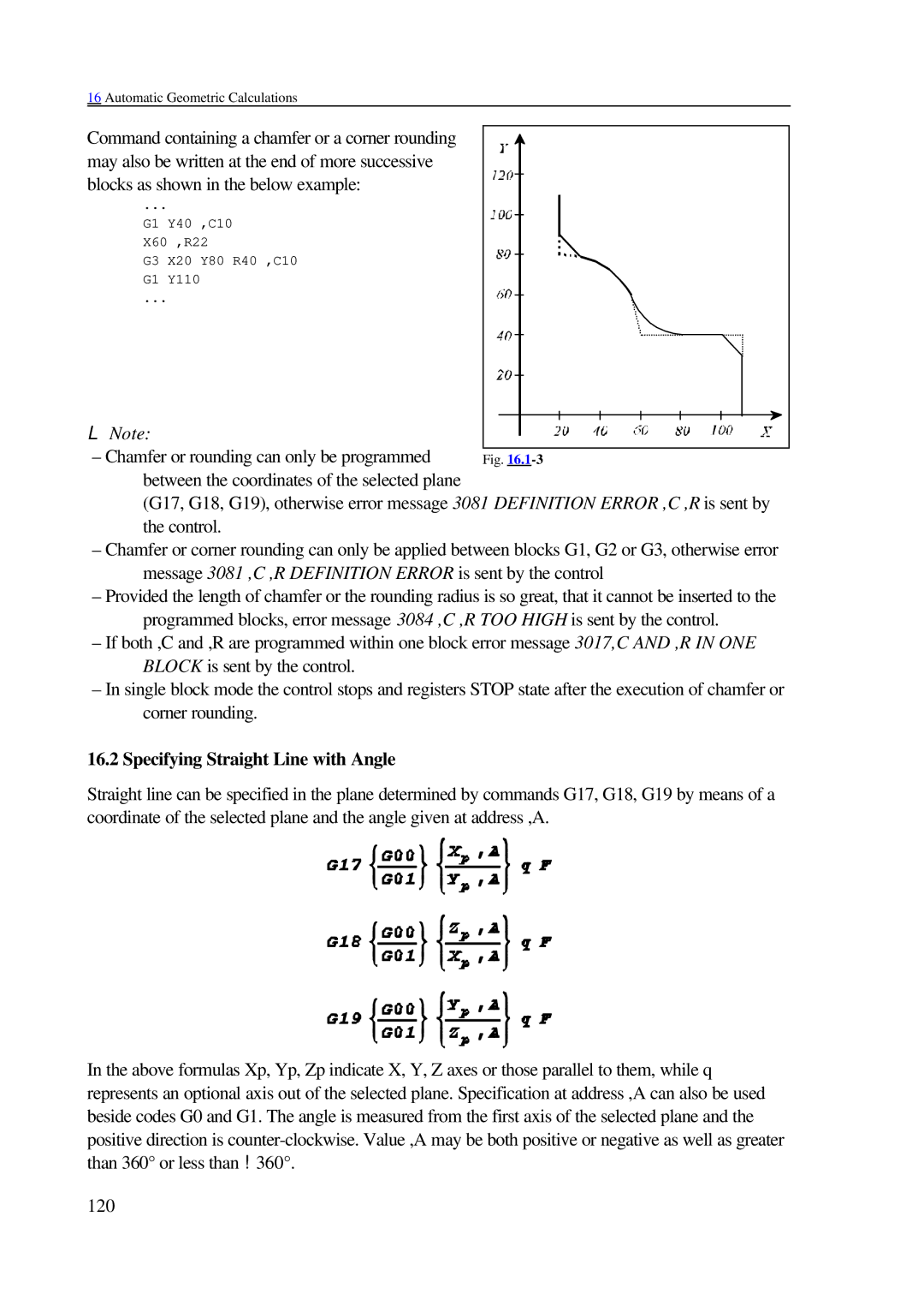
Command containing a chamfer or a corner rounding may also be written at the end of more successive blocks as shown in the below example:
...
G1 Y40 ,C10
X60 ,R22
G3 X20 Y80 R40 ,C10
G1 Y110
...
L Note:
– Chamfer or rounding can only be programmed between the coordinates of the selected plane
(G17, G18, G19), otherwise error message 3081 DEFINITION ERROR ,C ,R is sent by the control.
–Chamfer or corner rounding can only be applied between blocks G1, G2 or G3, otherwise error message 3081 ,C ,R DEFINITION ERROR is sent by the control
–Provided the length of chamfer or the rounding radius is so great, that it cannot be inserted to the programmed blocks, error message 3084 ,C ,R TOO HIGH is sent by the control.
–If both ,C and ,R are programmed within one block error message 3017,C AND ,R IN ONE BLOCK is sent by the control.
–In single block mode the control stops and registers STOP state after the execution of chamfer or corner rounding.
16.2 Specifying Straight Line with Angle
Straight line can be specified in the plane determined by commands G17, G18, G19 by means of a coordinate of the selected plane and the angle given at address ,A.
In the above formulas Xp, Yp, Zp indicate X, Y, Z axes or those parallel to them, while q represents an optional axis out of the selected plane. Specification at address ,A can also be used beside codes G0 and G1. The angle is measured from the first axis of the selected plane and the positive direction is
120