Installing the 201i server in the Succession 1000 systemStandard 1.07
Media Gateway and | Media Gateway and | ||
Media Gateway Expansion 3 | Media Gateway Expansion 4 | ||
Physical slot | Logical slot | Physical slot | Logical slot |
|
| ||
Media Gateway Expansion | Media Gateway Expansion | ||
|
|
|
|
7 | 37 | 7 | 47 |
8 | 38 | 8 | 48 |
9 | 39 | 9 | 49 |
10 | 40 | 10 | 50 |
|
|
|
|
Back panel connectors
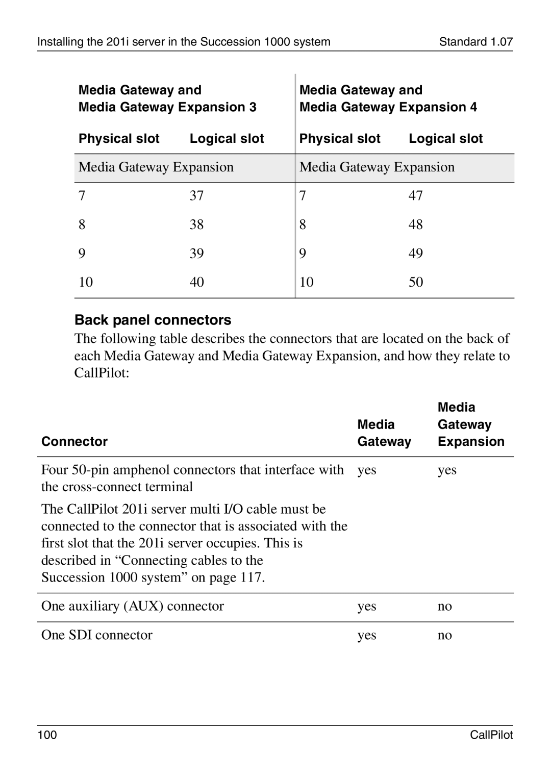
The following table describes the connectors that are located on the back of each Media Gateway and Media Gateway Expansion, and how they relate to CallPilot:
|
| Media |
| Media | Gateway |
Connector | Gateway | Expansion |
|
|
|
Four | yes | yes |
the |
|
|
The CallPilot 201i server multi I/O cable must be |
|
|
connected to the connector that is associated with the |
|
|
first slot that the 201i server occupies. This is |
|
|
described in “Connecting cables to the |
|
|
Succession 1000 system” on page 117. |
|
|
|
|
|
One auxiliary (AUX) connector | yes | no |
|
|
|
One SDI connector | yes | no |
100 | CallPilot |
