November 2006 | Installing the 201i server in a large Meridian 1 system |
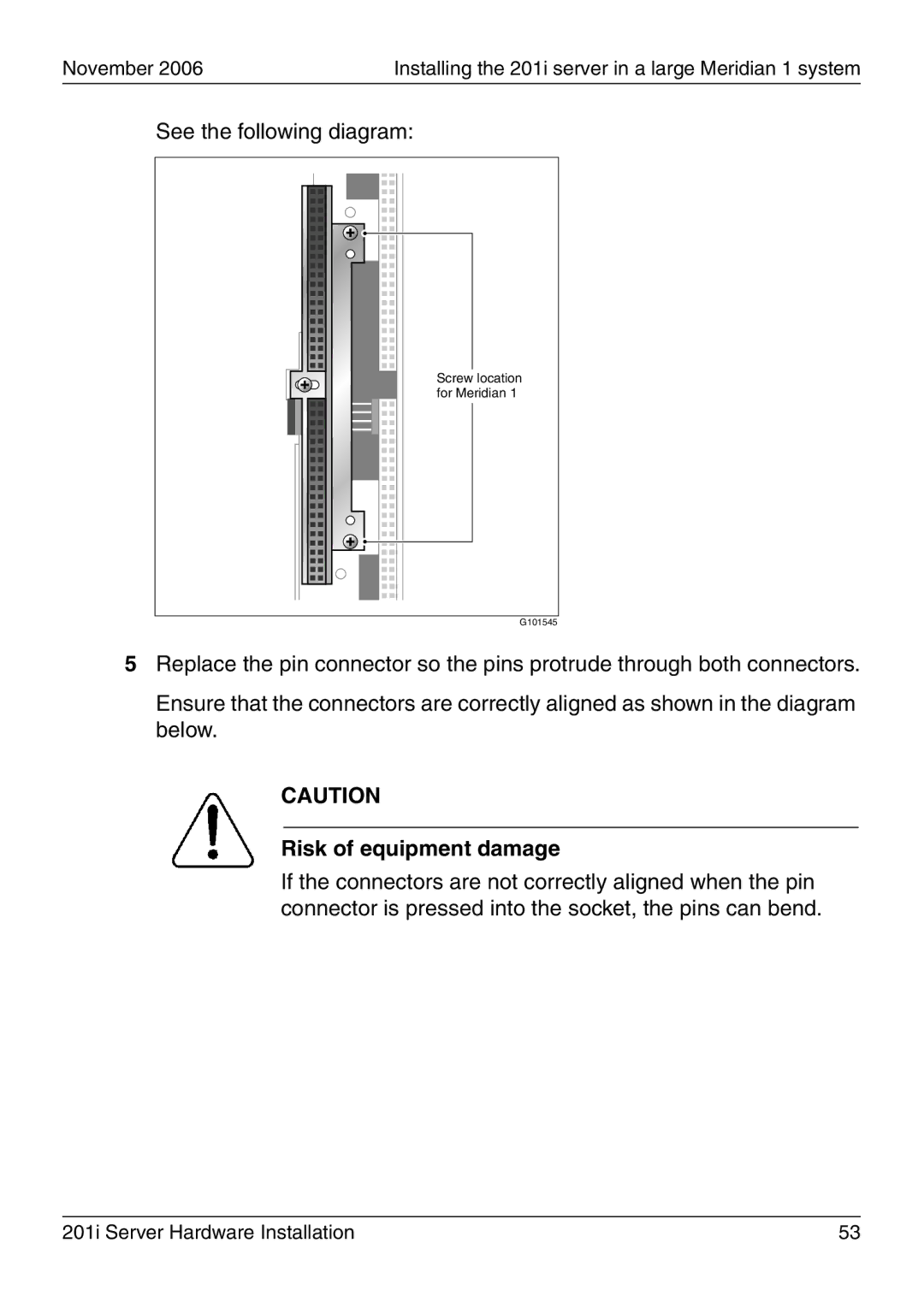
See the following diagram:
Screw location for Meridian 1
G101545
5Replace the pin connector so the pins protrude through both connectors.
Ensure that the connectors are correctly aligned as shown in the diagram below.
CAUTION
Risk of equipment damage
If the connectors are not correctly aligned when the pin connector is pressed into the socket, the pins can bend.
201i Server Hardware Installation | 53 |