November 2006 | Connecting peripheral devices to the 201i server |
2Attach the serial cable as follows:
a.Connect the
b.Attach the
c.Connect the
3Connect one end of the
CAUTION
Risk of equipment damage
Connect the modem to an analog line only. The use of a
4Plug the power cord into an electrical outlet with an isolated ground.
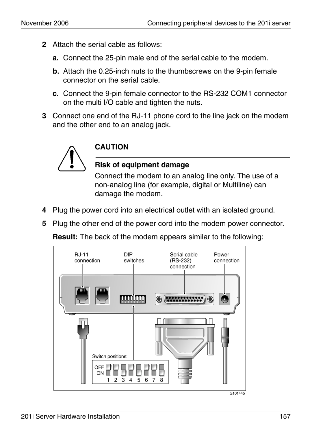
5Plug the other end of the power cord into the modem power connector. Result: The back of the modem appears similar to the following:
|
| DIP |
|
|
|
|
| Serial cable | Power | |||
connection |
|
| switches |
| connection | |||||||
|
|
|
|
|
|
|
|
|
|
| connection |
|
|
| 1 | 2 | 3 | 4 | 5 | 6 | 7 | 8 |
|
|
|
Switch positions: |
|
|
|
|
|
|
|
|
| |||
OFF |
|
|
|
|
|
|
|
|
|
|
|
|
ON |
|
|
|
|
|
|
|
|
|
|
|
|
1 | 2 | 3 |
| 4 |
| 5 | 6 | 7 | 8 |
| ||
|
|
|
|
|
|
|
|
|
|
|
| G101445 |
201i Server Hardware Installation | 157 |